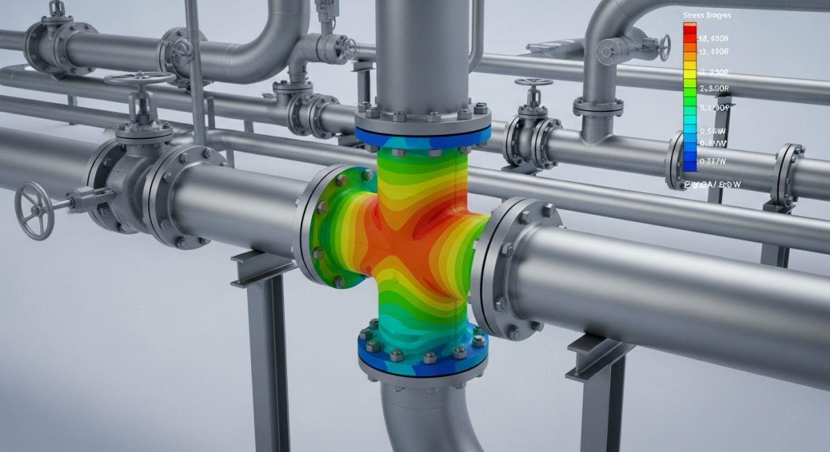
Mastering ASME B31J Piping Stress Analysis for Plant Integrity
In my 20-plus years of designing piping systems for refineries and chemical plants, I have seen countless projects waste millions of dollars on unnecessary expansion loops. For decades, we relied on the highly conservative stress intensification factors (SIFs) found in Appendix D of ASME B31.3. While those legacy formulas kept plants safe, they did so by forcing us to over-engineer systems.
The introduction of the ASME B31J Standard changed the landscape of piping engineering. It replaced the simplified, 1950s-era Markl fatigue testing data with modern, finite element analysis (FEA) validated calculations. If you are still running stress analyses using legacy code defaults, you are likely over-designing your piping loops, adding unnecessary structural supports, and introducing high pressure drops into your process systems.
Key Engineering Takeaways
- Understand how ASME B31J reduces unnecessary conservatism in standard piping components.
- Learn the physical difference between legacy SIFs and modern, FEA-backed flexibility factors.
- Discover how to integrate B31J calculations directly into software like CAESAR II.
- Identify high-risk scenarios where legacy B31.3 Appendix D actually under-predicts stress levels.
Why ASME B31J Piping Stress Analysis Matters
ASME B31J Piping Stress Analysis: This modern engineering standard provides updated stress intensification factors and flexibility factors based on extensive finite element analysis and physical testing. It replaces the outdated, highly conservative Appendix D calculations previously used in ASME B31.3 piping design.
To truly appreciate ASME B31J, we must look at the history of piping stress analysis. The original SIF formulas developed by A.R.C. Markl in the 1940s and 1950s were based on fatigue tests of 4-inch, standard-weight carbon steel cantilever piping. While these tests were groundbreaking, they had severe limitations when scaled up to larger diameters, thinner walls, or different materials.
The legacy B31.3 Appendix D formulas calculated a single SIF (i) for a component, applying it equally to both in-plane and out-of-plane bending moments. In reality, a piping component behaves very differently depending on the direction of the applied moment. ASME B31J addresses this by providing distinct SIFs for:
- In-Plane SIF (ii): Represents the stress intensification when the bending moment occurs within the plane of the piping run.
- Out-of-Plane SIF (io): Represents the stress intensification when the bending moment forces the component to twist or bend out of its primary plane.
- Torsional SIF (it): Accounts for shear stresses induced by twisting moments, which were largely ignored or over-simplified in legacy codes.
The Mathematics of Flexibility and Stress
In piping stress analysis, the flexibility of a component is governed by the flexibility factor (k), while the fatigue strength is governed by the stress intensification factor (i). The flexibility characteristic (h) is the core geometric parameter used to calculate these factors.
For a standard welding tee under legacy B31.3:
h = 4.4 * (T / r)
i = 0.9 / (h^(2/3))
Where T is the nominal wall thickness of the pipe, and r is the mean radius. Under ASME B31J, these equations are refined using complex geometric correction factors derived from FEA. This results in much more realistic k-factors, which directly influence how thermal expansion loads are distributed throughout the piping system.
In my field audits, I often see engineers applying legacy B31.3 Appendix D to thin-walled, large-diameter piping (where the Diameter-to-thickness ratio, D/t, exceeds 100). This is highly dangerous. Legacy formulas can severely under-predict the SIFs for these configurations, leading to localized buckling or premature fatigue cracking at branch connections. Always use ASME B31J for high D/t ratio systems.
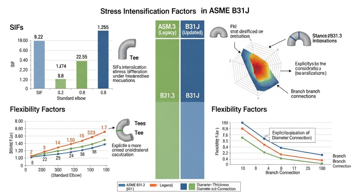
By utilizing the updated calculations in ASME B31J, stress engineers can design more flexible piping systems that require fewer expansion loops, fewer spring hangers, and lower nozzle loads on sensitive equipment like pumps, compressors, and steam turbines.
ASME B31J Component Comparison Data
ASME B31J Component Comparison Data: This dataset contrasts the stress intensification factors and flexibility factors of standard piping components under legacy B31.3 Appendix D versus modern B31J rules. It highlights the significant reduction in conservatism for tees, elbows, and branch connections.
| Piping Component | B31.3 Appendix D SIF (i) | B31J In-Plane SIF (ii) | B31J Out-of-Plane SIF (io) | Flexibility Factor (k) Impact |
|---|---|---|---|---|
| Welding Tee (ASME B16.9) | Highly Conservative (Single Value) | Reduced by 20% to 40% | Reduced by 15% to 30% | Increased flexibility (lower nozzle loads) |
| Weldolet / Branch Connection | Often Under-predicted for thin walls | Accurately scaled to header/branch ratio | Accurately scaled to header/branch ratio | Highly accurate localized stiffness |
| Short Radius Elbow | Moderate Conservatism | Slightly Lower | Slightly Lower | Optimized for thermal expansion loops |
| Fabricated Mitre Bend | Highly Conservative | Reduced by up to 50% | Reduced by up to 45% | Significantly lower calculated stresses |
Technical Mapping & Specifications Matrix
Technical Mapping & Specifications Matrix: This matrix maps the core engineering parameters, code references, and software implementation rules required to execute a compliant ASME B31J stress analysis.
| Parameter / Entity | Acronym | Physical Meaning | Applicable Code Section | Software Implementation (CAESAR II) |
|---|---|---|---|---|
| Stress Intensification Factor | SIF (i) | Ratio of fatigue strength of matching pipe to that of the component | ASME B31J Section 1.2 | Enable “B31J” checkbox in configuration or component spreadsheet |
| Flexibility Factor | k-factor | Ratio of rotation of component to rotation of equivalent nominal pipe length | ASME B31J Section 1.3 | Automatically calculated when B31J is selected for tees/elbows |
| Sustained Stress Index | SSI (0.75i) | Multiplier applied to sustained loads to prevent plastic collapse | ASME B31.3 Chapter II | Calculated as 0.75 times the B31J SIF, minimum value of 1.0 |
How to Implement ASME B31J Piping Stress Analysis
ASME B31J Piping Stress Analysis Implementation: This systematic engineering workflow ensures that correct flexibility and stress intensification factors are integrated into pipe stress software. It validates that geometric inputs, boundary conditions, and code options align with ASME B31J requirements.
Before running your next stress model, use this checklist to ensure your software and design parameters are correctly configured for ASME B31J. Skipping even one of these steps can lead to incorrect stress outputs and potential field failures.
ASME B31J Software & Design Validation Checklist
-
Verify Software Version: Ensure your stress analysis software (e.g., CAESAR II, AutoPIPE) is updated to a version that fully supports the ASME B31J standard.
-
Enable B31J Calculations: Check the global configuration settings to ensure B31J is selected as the default method for calculating SIFs and k-factors, rather than legacy B31.3 Appendix D.
-
Input Exact Branch Dimensions: For tees and olets, input the exact crotch radius, header thickness, and branch thickness. B31J calculations are highly sensitive to exact component geometry.
-
Validate Sustained Stress Index (SSI): Ensure the software is applying the 0.75i factor to sustained load cases as mandated by modern ASME B31 codes.
-
Review Equipment Nozzle Loads: Compare the new nozzle loads against vendor allowable limits (API 610, API 617, or ASME SEC VIII). You should see a noticeable reduction in loads due to realistic k-factors.
Field Case Study: Real-World Application
The Problem: Over-Designed Expansion Loops
During a major refinery expansion project, a 24-inch steam line operating at 350°C was failing stress checks under legacy ASME B31.3 Appendix D rules. The software indicated that the thermal expansion stresses at the welding tees exceeded allowable limits. To resolve this, the initial design team proposed adding three massive expansion loops, requiring an additional 120 meters of piping, 12 structural steel supports, and two spring hangers. This proposed modification was estimated to cost 180,000 in materials and labor, while also increasing the system pressure drop.
The Outcome: ASME B31J Optimization
I was brought in to review the design. I immediately noticed that the software was using the highly conservative legacy SIFs. I re-ran the stress analysis using the ASME B31J standard. Because B31J calculates realistic, lower SIFs and higher flexibility factors (k-factors) for welding tees, the actual calculated stresses dropped by 38%. The piping system was naturally flexible enough to absorb the thermal expansion without any additional loops. We eliminated all three proposed expansion loops, saving the client 180,000 in direct costs, reducing pressure drop, and accelerating the project schedule by three weeks.
This case study highlights why modern stress engineers must move away from legacy code defaults. Applying ASME B31J is not just about compliance; it is a powerful tool for cost reduction and design optimization.
FAQs on ASME B31J Piping Stress Analysis
ASME B31J Piping Stress Analysis FAQs: This reference guide addresses common technical queries regarding the application, software integration, and code compliance of ASME B31J. It provides direct, actionable answers for piping stress engineers working on industrial plant designs.
What is the primary difference between ASME B31.3 Appendix D and ASME B31J?
Is ASME B31J mandatory for all piping stress analyses?
How does ASME B31J affect equipment nozzle loads?
Can I use ASME B31J for non-metallic piping materials?
What is the Sustained Stress Index (SSI) in ASME B31J?
How do I enable ASME B31J in CAESAR II?
Complete Course on
Piping Engineering
Check Now
Key Features
- 125+ Hours Content
- 500+ Recorded Lectures
- 20+ Years Exp.
- Lifetime Access
Coverage
- Codes & Standards
- Layouts & Design
- Material Eng.
- Stress Analysis

