Table of Contents
What is a Cryogenic Valve in Piping Systems?
In my 20 years of piping engineering, I have seen many systems fail because engineers treated cryogenic service like standard low-temperature utility lines. When you are dealing with Liquid Natural Gas (LNG) at -162 degrees Celsius or liquid nitrogen at -196 degrees Celsius, standard valves fail instantly. The elastomer seals turn brittle as glass, the metal contracts unevenly, and the packing freezes solid, locking the valve in place. That is where a specialized cryogenic valve becomes the backbone of your piping system.
Key Engineering Takeaways
- Extended bonnets are mandatory to keep stem packing warm and functional.
- Cavity pressure relief is non-negotiable to prevent explosive overpressure.
- Material selection must prioritize austenitic stainless steels to avoid brittle fracture.
Why Use a Cryogenic Valve in Piping?
Cryogenic Valve Selection: The process of integrating extended-bonnet valves into low-temperature piping systems to prevent stem packing freeze-up and ensure thermal insulation integrity under ASME B16.34 design rules.
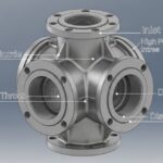
The physics of cryogenic fluids demand unique mechanical solutions. When liquid cryogens are trapped in a closed cavity, such as the body cavity of a closed ball or gate valve, they absorb ambient heat and vaporize. The expansion ratio of LNG is roughly 1 to 600. If trapped, this phase change generates catastrophic pressures exceeding 1000 bar, which can rupture the valve body.
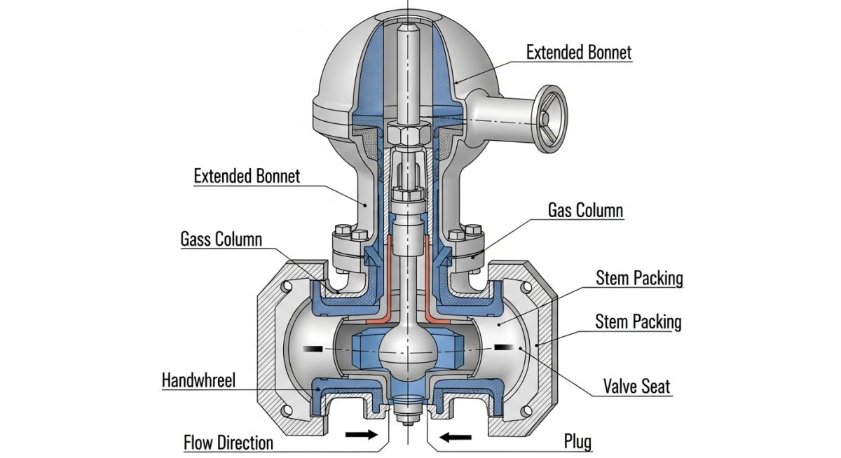
The Gas Column Principle (Extended Bonnet)
The bonnet must be long enough to position the stem packing far enough from the cold process fluid. This allows a column of vaporized gas to form inside the bonnet. This gas column acts as a natural insulator, keeping the packing close to ambient temperature (above 0 degrees Celsius) so the packing remains resilient and prevents leaks.
Bonnet Length Calculation
To calculate the required bonnet length, we analyze the heat transfer along the bonnet. The heat flow (Q) from the ambient air to the cryogenic fluid must be balanced by the heat conducted through the bonnet wall and stem. The formula is:
Q = (k * A * (T_ambient – T_process)) / L
Where k is the thermal conductivity of the bonnet material (typically 15 W/m-K for 316 stainless steel), A is the cross-sectional area of the metal, and L is the bonnet length. To keep the packing temperature above the freezing point of water (273 Kelvin), the length L must satisfy the inequality:
L >= (k * A * (T_packing – T_process)) / (h * P * (T_ambient – T_packing))
Where h is the natural convection heat transfer coefficient of ambient air and P is the outer perimeter of the bonnet.
Austenitic stainless steels (such as ASTM A351 CF8M or CF8) contract significantly at -196 degrees Celsius. The linear thermal contraction coefficient of 316 SS is approximately 16 x 10^-6 m/m-K. For a 10-inch valve, this contraction can cause severe binding if the stem and body contract at different rates. Therefore, precise clearances must be maintained during the design phase in accordance with ASME B31.3 and BS 6364.
| Component | Recommended Material | ASTM Specification | Min Temp Rating | Engineering Justification |
|---|---|---|---|---|
| Body & Bonnet | 316 Stainless Steel | ASTM A351 CF8M | -196 °C | Excellent impact strength; no ductile-to-brittle transition. |
| Stem | XM-19 (Nitronic 50) | ASTM A479 | -196 °C | High yield strength and low friction coefficient at low temperatures. |
| Seat Insert | PCTFE (Kel-F) | Proprietary Polymer | -250 °C | Retains ductility and sealing capability at extreme low temperatures. |
| Stem Packing | Die-formed Graphite | Flexible Graphite | -196 °C to +200 °C | Low emission sealing with PTFE wiper rings to prevent moisture ingress. |
| Valve Type | Cryogenic Suitability | Primary Application | Leakage Class (BS 6364) | Key Design Standard |
|---|---|---|---|---|
| Globe Valve | Excellent | Throttling & Isolation | Class A (Zero Leakage) | BS 6364 |
| Ball Valve | Good (With Cavity Relief) | Quick Isolation | Class A | API 6D / ISO 28921 |
| Butterfly Valve | Excellent (Triple Offset) | Large Bore Isolation | Class A | API 609 |
| Gate Valve | Moderate | Large Bore Isolation | Class B | ASME B16.34 |
How to Select a Cryogenic Valve Safely
Cryogenic Valve Verification: A systematic field inspection protocol to verify valve orientation, cavity relief functionality, and packing integrity prior to cold box installation under API 598 testing guidelines.
Before installing any cryogenic valve into a cold box or piping manifold, field engineers must execute a rigorous verification protocol. Failure to do so often results in expensive cut-outs and project delays.
Pre-Commissioning Field Checklist
-
Verify Flow Direction & Cavity Relief: Ensure the cavity relief hole on the ball or gate points toward the high-pressure upstream side to prevent pressure trapping.
-
Confirm Bonnet Extension Angle: The valve stem must be installed at an angle of at least 45 degrees from the horizontal (ideally vertical) to maintain the insulating gas column.
-
Perform Helium Leak Test: Execute a helium leak test at cryogenic temperatures per BS 6364 before final insulation.
-
Check Stem Packing Torque: Verify that the stem packing is adjusted to the manufacturer’s torque specification to prevent binding at low temperatures.
-
Inspect Drip Collar Integrity: Ensure the drip collar is welded securely below the packing gland to divert condensation away from the insulation.
Field Case Study: Real-World Application
The Problem: LNG Terminal Valve Seizure
An LNG receiving terminal experienced repeated failures of 8-inch cryogenic ball valves during cool-down operations. The valves became completely stuck, and thermal imaging revealed that the stem packing area was freezing over, covered in thick ice. This caused the pneumatic actuators to stall, risking a major plant shutdown.
The Outcome: Redesign & Re-Orientation
I led the investigation and found two critical errors. First, the valves were installed horizontally, which allowed liquid LNG to flood the extended bonnet, destroying the insulating gas column and freezing the packing. Second, the valves lacked cavity relief holes, trapping liquid inside the ball. We re-installed the valves vertically, replaced the seals with PCTFE, and drilled a 3mm cavity relief hole on the upstream side of the ball. The system has now operated for 5 years without a single freeze-up or seizure.
This case highlights why proper engineering design and installation practices are critical. Simply buying a certified cryogenic valve is not enough; you must understand how it interacts with the piping system layout.
Frequently Asked Engineering Questions
What is the purpose of the extended bonnet on a cryogenic valve?
Why is helium used for cryogenic valve testing instead of water or air?
Can we install a cryogenic valve horizontally?
What is cavity pressure relief, and why is it critical for LNG?
What are the primary differences between BS 6364 and API 598?
Which materials are completely banned in cryogenic valve construction?
Complete Course on
Piping Engineering
Check Now
Key Features
- 125+ Hours Content
- 500+ Recorded Lectures
- 20+ Years Exp.
- Lifetime Access
Coverage
- Codes & Standards
- Layouts & Design
- Material Eng.
- Stress Analysis

📚 Recommended Resources: cryogenic valve
Read these Guides
🎓 Advanced Training


Related posts:
![Piping stress engineer analyzing 3D piping model on computer screen for stress analysis]()
Mastering Piping Stress Interview Questions: The Ultimate Engineering Guide
![Industrial steam jet ejector 3D CAD model showing inlet and discharge ports]()
What is an Ejector? Types, Parts, Datasheet, and Working Principles
![3D CAD model of industrial piping system showing color-coded piping classes and specifications.]()
Mastering the Piping Material Specification for Industrial Plant Design
![Industrial pig launcher and receiver station with quick-opening closure and bypass piping.]()
Design and Engineering of Pig Launchers and Receivers
![Close-up of an industrial dial pressure gauge mounted on a stainless steel pipe.]()
What is a Pressure Gauge and How Does It Work?
![3D cutaway diagram of an industrial ball valve showing internal components like the ball, stem, and seats.]()
What is a Ball Valve? Design, Types, and Engineering Standards