Designing a Compressed Air System for Maximum Industrial Efficiency
In my 20-plus years of piping engineering, I have walked into hundreds of manufacturing plants where the compressor room was screaming, pressure drops were killing production, and the energy bill was astronomical. More often than not, the culprit is not a failing compressor, but a poorly designed distribution network. A compressed air system is often referred to as the fourth utility in industrial facilities, yet it is frequently the most misunderstood and least optimized.
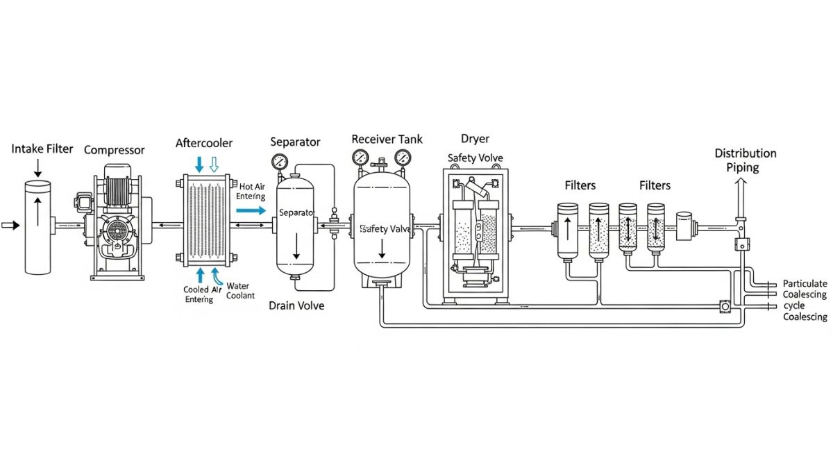
When we design these systems, we must look beyond the compressor package itself. We have to analyze the entire lifecycle of the air molecule, from the moment it enters the intake filter to its final expansion at the pneumatic tool. This guide draws on my field experience to walk you through the exact calculations, layout strategies, and optimization techniques required to build a world-class, energy-efficient distribution network.
Key Engineering Takeaways
- Learn how to calculate actual system demand using the Free Air Delivery method.
- Understand the critical role of wet and dry air receivers in managing pressure fluctuations.
- Master the empirical formulas used to size distribution headers and drop lines.
- Identify the optimal piping materials to prevent corrosion and pressure drop.
- Discover how to implement a closed-loop ring main to balance flow and pressure.
How to Size a Compressed Air System Correctly
Sizing a system begins with establishing the total air consumption. I always advise engineers to compile a detailed equipment list with individual flow rates (expressed in Standard Cubic Feet per Minute, or SCFM) and operating pressures. However, simply summing these values leads to massive over-sizing. You must apply a diversity factor, which accounts for the reality that not all tools operate simultaneously.
Step 1: Calculating Total Volumetric Flow (FAD)
To find the required Free Air Delivery (FAD) of your compressor, use the following formula:
Where:
- Q_tool: Rated air consumption of each individual pneumatic device.
- DF_tool: Diversity factor of the tool (typically ranging from 0.1 for intermittent tools to 0.9 for continuous process equipment).
- Leakage_Allowance: Typically 0.10 (10%) for a well-maintained new system, but can be as high as 0.30 for older networks.
- Future_Expansion_Factor: Typically 0.15 to 0.20 to prevent system obsolescence within 5 years.
Step 2: Determining Pipe Diameter and Pressure Drop
Once the total flow rate is established, we must size the piping network. The goal is to keep the total pressure drop from the compressor room to the furthest point of use below 0.3 bar (approx. 4.3 psi). To calculate the pressure drop in a straight run of pipe, we use the simplified empirical formula for compressed air:
Where:
- dP: Pressure drop in bar.
- q: Flow rate in liters of free air per second (l/s).
- L: Equivalent length of the pipe run in meters (including fittings).
- d: Inside diameter of the pipe in millimeters.
- P: Initial absolute pressure in bar (gauge pressure plus 1.013 bar).
In my practice, I often see designers size pipes based solely on pressure drop calculations, completely ignoring velocity. If the air velocity exceeds 10 meters per second (m/s) in the main header, it will carry moisture and pipe scale directly to your tools, causing premature component failure. Keep main header velocities between 6 and 10 m/s, and branch lines under 15 m/s.
Piping Layout and Material Selection
The layout of your piping network heavily influences its efficiency. I always recommend a closed-loop ring main (or loop system) for industrial plants. This design allows air to flow in two directions to reach any given point of consumption, effectively cutting the air velocity and pressure drop in half.
When selecting materials, we must balance cost, weight, and corrosion resistance. While carbon steel (black iron) is traditional, it is prone to internal rust when exposed to moisture, which ruins downstream filters. Aluminum piping has become the modern standard because it is lightweight, corrosion-resistant, and has a very low friction coefficient, which reduces pressure drop over time.
All piping designs must comply with ASME B31.1 for power piping or ASME B31.3 for process piping, depending on the facility type. Air receivers must be designed and stamped in accordance with the ASME Boiler and Pressure Vessel Code, Section VIII, Division 1.
The following tables provide the standard design limits and velocity parameters that I use during the front-end engineering design (FEED) phase of any industrial compressed air system.
| System Section | Recommended Velocity (m/s) | Maximum Velocity (m/s) | Target Pressure Drop (bar) |
|---|---|---|---|
| Compressor Room Interconnections | 3.0 to 4.5 | 6.0 | < 0.05 |
| Main Distribution Header (Ring Main) | 6.0 to 10.0 | 12.0 | < 0.10 |
| Branch Distribution Lines | 8.0 to 12.0 | 15.0 | < 0.10 |
| Equipment Drop Lines (Final Connection) | 10.0 to 15.0 | 20.0 | < 0.05 |
| Technical Entity | Acronym | Physical Parameter | Standard Reference | Design Limit / Rule of Thumb |
|---|---|---|---|---|
| Free Air Delivery | FAD | Volumetric Flow Rate (m3/min or CFM) | ISO 1217 | Measured at ambient inlet conditions (1 bar, 20 deg C) |
| Pressure Dew Point | PDP | Temperature (deg C or deg F) | ISO 8573-1 Class 1-4 | Class 4 requires +3 deg C; Class 2 requires -40 deg C |
| Receiver Vessel Volume | V_rec | Capacity (Liters or Gallons) | ASME Sec VIII Div 1 | 3 to 4 gallons per CFM of compressor capacity |
| Air Purity Classes | ISO Class | Particulate, Water, Oil concentration | ISO 8573-1 | Specifies maximum allowable contaminants per cubic meter |
Optimizing Your Compressed Air System for Energy Savings
Before you commission any newly installed or modified distribution network, you must perform a rigorous field verification. Skipping this step almost guarantees that minor installation errors will turn into major operational headaches. I have developed this checklist over years of troubleshooting systems that failed to meet their design specifications.
Pre-Commissioning & Optimization Checklist
Ensure all horizontal distribution lines are sloped at 1% (10 mm per meter) down in the direction of air flow. This allows condensed water to migrate to low-point drain traps rather than pooling in the main header.
Verify that all branch lines and drop lines exit from the top of the main header (using a 180-degree bend or “swan-neck”). This prevents liquid water running along the bottom of the header from dropping into pneumatic tools.
Confirm that safety relief valves are certified under ASME Section VIII and set to open at 10% above the maximum operating pressure, but never exceeding the Maximum Allowable Working Pressure (MAWP) of the vessel.
Check that all automatic drains on the wet receiver, filters, and dryer are electronic zero-loss level-sensing drains. Avoid timed solenoid valves, which waste massive amounts of compressed air when they open.
Perform a full system pressure test at nominal operating pressure using an ultrasonic leak detector. Tag and repair any leak showing a decibel level above ambient background noise.
Field Case Study: Real-World Application
At a heavy automotive assembly plant in Ohio, the production line suffered from frequent pneumatic tool failures and low-pressure alarms. The plant operators believed their 150 HP rotary screw compressor was failing and planned to purchase an additional 100 HP unit at a cost of 85,000.
Upon auditing the site, I discovered they had a straight-line (dead-end) header design. When the sandblasting station at the end of the line cycled on, the pressure at the final drop plummeted from 7.0 bar to 4.8 bar. The velocity in the 2-inch main header was clocked at an astronomical 22 m/s, which was carrying liquid water and pipe scale directly into the precision torque tools.
Instead of buying a new compressor, we redesigned the distribution network. We converted the dead-end header into a 3-inch aluminum closed-loop ring main. We also installed a 2,000-gallon dry air receiver tank immediately upstream of the high-demand sandblasting station to act as a local buffer.
This modification reduced the maximum air velocity in the main header to 5.5 m/s and stabilized the pressure drop across the entire plant to less than 0.15 bar. The plant was able to turn off one of their smaller backup compressors entirely, saving them over 24,000 annually in electricity costs, with a total project payback period of just 9 months.
My recommendation for any facility experiencing localized pressure drops is to look at storage and piping geometry before investing in more compressor horsepower. Adding a local receiver tank near a high-intermittent-demand application is almost always more cost-effective than sizing the entire upstream system for peak instantaneous flow.
Frequently Asked Engineering Questions
What is the difference between a wet receiver and a dry receiver?
Why is aluminum piping preferred over black iron or galvanized steel?
How do I determine the correct size for an air receiver tank?
What are the air quality classes defined under ISO 8573-1?
Can I use PVC piping for compressed air distribution?
How does pressure drop affect my compressor’s energy consumption?
Complete Course on
Piping Engineering
Check Now
Key Features
- 125+ Hours Content
- 500+ Recorded Lectures
- 20+ Years Exp.
- Lifetime Access
Coverage
- Codes & Standards
- Layouts & Design
- Material Eng.
- Stress Analysis

📚 Recommended Resources: compressed air system
Read these Guides


Related posts:
![Industrial piping manifold showing different types of pipe joints including flanged and welded connections.]()
Mastering the Core Types of Pipe Joints in Industrial Piping
![CNC rotary draw tube bending machine shaping a stainless steel pipe in a manufacturing facility.]()
What is Tube Bending? Working, Types, and Industrial Applications
![Cross-section comparison of a metallurgically bonded clad pipe and a mechanically bonded lined pipe.]()
What is Cladded Pipe? Difference Between Clad and Lined Pipe
![Conceptual illustration of digital technical data exchange between an engineering office and a process equipment vendor.]()
How to Manage Technical Information Exchange With Process Equipment Vendors
![3D piping stress analysis of a Smart Tee model in START-PROF software.]()
Mastering Smart Tee Model Considerations in START-PROF Stress Analysis
![Coated industrial bolts on an offshore pipeline flange showing corrosion protection.]()
Coating Selection for External Bolting to Reduce Corrosion in Piping