Table of Contents
What is a Cold Box in Cryogenic Plant Systems?
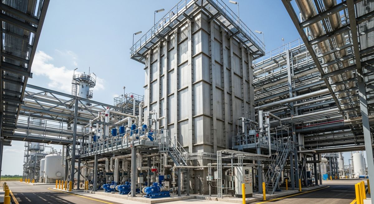
In my 20+ years of piping engineering, standing on a cold, windy site watching a massive 150-foot cold box being erected is always a humbling experience. To the untrained eye, it looks like a giant, featureless metal skyscraper. But to those of us who design and commission them, it is a masterpiece of thermal isolation. A cold box is the beating heart of any modern Air Separation Unit (ASU). It houses the delicate, ultra-cold distillation columns and heat exchangers that split ordinary air into high-purity oxygen, nitrogen, and argon.
When you are dealing with fluids at minus 196 degrees Celsius, standard insulation like fiberglass or polyurethane foam is completely useless. The temperature differential between the inside of the columns and the outside air is often greater than 220 degrees Celsius. At these extremes, ambient heat tries to rush in with incredible force. If even a fraction of that heat penetrates the system, the cryogenic liquids instantly vaporize, halting the entire separation process. That is why we package these components inside a sealed, insulated structural casing—the cold box.
Key Engineering Takeaways
- Thermal Isolation: The primary function is to eliminate convective, conductive, and radiative heat transfer into the cryogenic process.
- Structural Integrity: The outer casing must support massive internal loads while resisting wind, seismic forces, and internal purge pressures.
- Material Selection: Internal piping and vessels must use materials that do not undergo ductile-to-brittle transition, such as 304L Stainless Steel and Aluminum 5083.
- Insulation Media: Utilizes compacted perlite powder combined with a dry nitrogen purge gas to eliminate moisture and oxygen ingress.
- Thermal Contraction: Piping layouts must accommodate significant physical shrinkage as the system cools from ambient to cryogenic operating temperatures.
Designing a Cold Box in Cryogenic Plant
When designing a cold box, we are fighting a constant battle against physics. The design is governed by strict international standards, primarily ASME B31.3 (Process Piping) and ASME Section VIII (Pressure Vessels). The outer shell is typically constructed of carbon steel plates stiffened with structural beams. However, the internals are a completely different story.
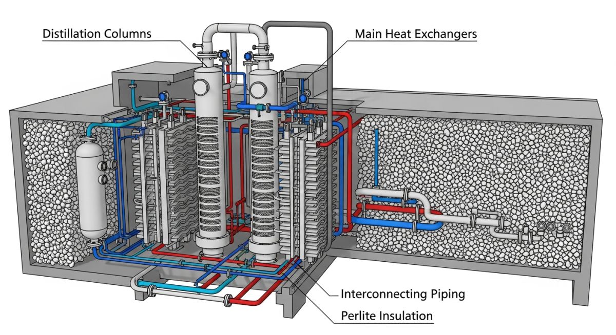
The primary internal components include:
- Brazed Aluminum Heat Exchangers (BAHX): Often called plate-fin heat exchangers, these provide an incredibly high surface-area-to-volume ratio, allowing rapid heat transfer between incoming warm air and outgoing cold product streams.
- Distillation Columns: Vertical pressure vessels where fractional distillation occurs. The high-pressure column sits at the bottom, and the low-pressure column sits at the top, separating air into its constituent gases based on boiling points.
- Cryogenic Piping: The interconnecting lines that transport liquid and gaseous oxygen, nitrogen, and argon. These must be designed with extreme flexibility to handle thermal contraction.
The Mathematics of Cryogenic Thermal Contraction
One of the most critical aspects of cold box design is calculating and managing thermal contraction. When a stainless steel or aluminum pipe cools from an ambient installation temperature of 25 degrees Celsius to an operating temperature of minus 196 degrees Celsius, it shrinks significantly.
Let us look at a real-world design calculation. Suppose we have a vertical liquid nitrogen transfer line made of ASTM A312 Grade TP304L Stainless Steel.
– Pipe Material: Stainless Steel 304L
– Total Vertical Length (L): 35 meters
– Installation Temperature (T1): 25 °C (298 K)
– Operating Temperature (T2): -196 °C (77 K)
– Temperature Differential (Delta T): T2 – T1 = -221 °C
– Mean Coefficient of Thermal Expansion (alpha) for 304L SS from 25°C to -196°C: 14.7 x 10^-6 m/m-K
Formula:
Delta L = L * alpha * Delta T
Calculation:
Delta L = 35 m * (14.7 x 10^-6 / °C) * (-221 °C)
Delta L = 35 * 0.0000147 * -221
Delta L = -0.1137 meters
Delta L = -113.7 mm
A contraction of over 113 millimeters (nearly 4.5 inches) on a single vertical run is massive! If this pipe were rigidly anchored at both ends, the resulting thermal stresses would easily exceed the allowable yield strength of the material, leading to a catastrophic structural rupture.
To resolve this, we never run straight lines between fixed points inside a cold box. We design engineered piping loops, offsets, and expansion bends. We also utilize “cold spring” techniques, where the piping is intentionally cut short and pulled into tension during ambient installation, so that it relaxes into a neutral, low-stress state when it reaches its ultra-cold operating temperature.
CRITICAL FIELD WARNING: Bellows Expansion Joints
In my career, I have seen junior engineers attempt to solve thermal contraction inside cold boxes by specifying bellows expansion joints. This is a dangerous practice. Bellows are thin-walled components prone to fatigue failure and stress corrosion cracking. Because the cold box is packed tight with perlite insulation, accessing a failed bellows for repair requires a complete plant shutdown, perlite evacuation, and structural cutting. Always prioritize piping flexibility loops over mechanical expansion joints inside the cold box casing.
Insulation and Purging Systems
To prevent heat transfer, the entire volume of the cold box surrounding the vessels and piping is filled with expanded perlite. Perlite is an inorganic, volcanic glass that expands when heated, forming a lightweight powder with extremely low thermal conductivity.
However, perlite alone is not enough. Ambient air contains moisture and carbon dioxide. If air leaks into the cold box, the moisture and CO2 will freeze solid on the cryogenic surfaces, creating ice blocks that can crush piping, block valves, and destroy the insulation’s thermal properties. To prevent this, the cold box is continuously purged with dry nitrogen gas at a slight positive pressure (typically 5 to 20 mbar). This positive pressure ensures that any leakage is dry nitrogen flowing outward, rather than moist atmospheric air leaking inward.
Selecting the correct materials for cryogenic service is a highly regulated process. Carbon steel becomes extremely brittle at temperatures below minus 29 degrees Celsius, making it completely unsuitable for internal cold box piping. The table below outlines the standard materials we specify for cryogenic cold box internals.
| Material Grade | ASTM Standard | Min. Temp Limit (°C) | Thermal Conductivity (W/m-K at 100K) | Primary Application |
|---|---|---|---|---|
| Stainless Steel 304L | ASTM A312 | -254 °C | 9.8 | High-pressure cryogenic piping, liquid headers |
| Aluminum 5083-O | ASTM B209 | -269 °C | 64.0 | Distillation column shells, low-pressure piping |
| Aluminum 6061-T6 | ASTM B241 | -269 °C | 78.0 | Structural supports, internal bracing, small nozzles |
| Copper (C10200) | ASTM B75 | -273 °C | 482.0 | Instrument tubing, specialized heat exchanger components |
Technical Mapping & Specifications Matrix
To ensure seamless integration between structural, mechanical, and process disciplines, we use a comprehensive mapping matrix during the detailed engineering phase.
| System Component | Primary Function | Design Code / Standard | Key Engineering Parameter |
|---|---|---|---|
| Brazed Aluminum Heat Exchanger (BAHX) | Thermal exchange between warm feed air and cold product streams | ASME Sec VIII Div 1 / ALPEMA | Maximum allowable working pressure (MAWP) and thermal approach temperature |
| Distillation Columns | Fractional distillation of liquefied air components | ASME Sec VIII Div 1 | Tray/packing efficiency, liquid distributor leveling tolerance |
| Perlite Insulation | Minimizing conductive and convective heat ingress | CGA G-4.1 / ASTM C549 | Bulk density (typically 48 to 96 kg/m³) and moisture content (< 0.5%) |
| Purge Gas System | Maintaining positive dry nitrogen pressure inside the casing | NFPA 55 / CGA G-10.1 | Dew point of purge gas (must be below -60 °C) and casing relief valve setting |
Maintaining a Cold Box in Cryogenic Plant
Before we load perlite or introduce cryogenic liquids into the system, we must execute a rigorous pre-commissioning protocol. Any mistake left uncorrected inside the cold box will be buried under tons of perlite, making future corrections incredibly expensive and time-consuming.
Pre-Commissioning Field Checklist
-
Pneumatic Leak Testing: Perform pneumatic strength and leak testing of all internal piping systems in strict accordance with ASME B31.3 Section 345.5. Use dry nitrogen or oil-free dry air; never use water for testing cryogenic lines.
-
Helium Leak Detection: Execute a helium mass spectrometer leak test on all critical brazed joints and transition joints (aluminum-to-stainless steel) to detect micro-leaks that standard bubble-testing might miss.
-
Cold Box Casing Integrity: Inspect the structural welds of the outer carbon steel casing. Perform a low-pressure soap bubble test on the casing seams at 50 mbar to ensure zero atmospheric air ingress paths.
-
Perlite Dryness Verification: Verify that the perlite loading system is completely dry. Measure the moisture content of the perlite before blowing it into the cold box; it must be less than 0.5% by weight.
-
Purge Gas Dew Point Check: Establish the nitrogen purge on the cold box casing and monitor the outlet gas dew point. The system is only ready for cool-down when the outlet dew point remains consistently below minus 60 degrees Celsius.
-
Instrument Calibration: Calibrate all internal temperature elements (typically RTDs) and differential pressure transmitters. Ensure that all capillary lines are properly sloped and heat-traced at the cold box penetration plate to prevent freezing.
Field Case Study: Real-World Application
The Problem: Casing Frosting and Purge Pressure Loss
At a 1,500 ton-per-day Air Separation Unit in the Middle East, the operations team noticed a sudden drop in the cold box casing nitrogen purge pressure, accompanied by a massive, localized frost spot forming on the outer carbon steel casing plate about 40 feet up. Within 48 hours, the frost spot turned into a thick ice block. This indicated a major internal cryogenic liquid leak. Liquid nitrogen was leaking into the perlite, vaporizing, and cooling the outer carbon steel casing below its ductile-to-brittle transition temperature of minus 29 degrees Celsius, risking a catastrophic structural collapse of the cold box tower.
The Outcome: Safe Shutdown, Repair, and Piping Redesign
I was called to the site to lead the emergency engineering response. We immediately initiated a controlled plant shutdown and began the “derime” (warm-up) process by purging the internals with warm nitrogen gas. Once the system reached ambient temperature, we safely vacuumed out over 120 tons of perlite insulation into temporary storage silos.
Upon entering the cold box, we discovered a clean, circumferential crack on a 4-inch liquid nitrogen line leading from the low-pressure column. The root cause was thermal fatigue. The piping designer had not provided sufficient flexibility in the horizontal run, and the pipe was binding against an internal structural support beam during cool-down.
We cut out the damaged section and welded a new spool piece using Gas Tungsten Arc Welding (GTAW) with ER308L filler metal. We performed 100% radiography and dye penetrant testing on the new welds. Most importantly, we redesigned the piping support, replacing the rigid guide with a sliding Teflon-lined shoe to allow unrestricted thermal movement. After reloading the perlite and establishing a dry nitrogen purge, the plant restarted successfully. The casing remained completely frost-free, and purge pressure stabilized.
This case study highlights why we must never compromise on piping flexibility analysis during the design phase. A single restricted pipe support can cause millions of dollars in lost production and emergency repair costs.
Frequently Asked Engineering Questions
Why is carbon steel not used for internal cold box piping?
What is the purpose of the nitrogen purge gas system?
How is perlite insulation loaded and compacted?
What is a transition joint in a cold box?
How do you detect an internal leak during operation?
What is the “derime” process in a cryogenic plant?
===FAQ_BLOCK===
Complete Course on
Piping Engineering
Check Now
Key Features
- 125+ Hours Content
- 500+ Recorded Lectures
- 20+ Years Exp.
- Lifetime Access
Coverage
- Codes & Standards
- Layouts & Design
- Material Eng.
- Stress Analysis

📚 Recommended Resources: cold box in cryogenic plant
Read these Guides
Related posts:
![A mechanical sucker rod pumpjack operating in an oil field at sunset]()
What is Sucker Rod Pump System in Oil Production?
![Piping material engineer reviewing technical specifications on a tablet in an industrial plant.]()
How a Piping Material Engineer Drives Industrial Project Success
![Industrial refinery plant showing various types of static equipment]()
What is Static Equipment? Types and List of Static Equipments
![Side-by-side comparison of industrial process piping and power plant steam piping systems.]()
Differences Between ASME B31.3 and B31.1: B31.3 vs B31.1
![Large industrial steel storage tank under construction with cranes and scaffolding]()
Storage Tank Construction Method Statement: Step-by-Step Engineering Guide
![Cutaway diagram of a globe control valve highlighting the internal valve trim components]()
What is a Valve Trim? Types, Components, and Selection


