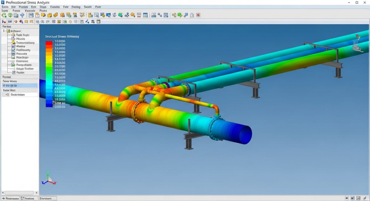
Caesar II Stress Analysis for Thin-Walled Piping Systems
In my two decades of piping stress analysis, I have frequently encountered the “thin-walled” challenge. When the diameter-to-thickness (D/t) ratio crosses the 100 threshold, standard beam theory assumptions often begin to falter. Caesar II is a powerful tool, but it is not a magic wand for thin-walled structures where local shell buckling becomes a dominant failure mode rather than simple bending stress.
Engineers often rely on default software settings, which can lead to dangerous underestimations of local stresses. When dealing with large-diameter, thin-walled lines, we must manually verify the validity of the flexibility factors and stress intensification factors (SIFs) that the software automatically applies. This article explores how to bridge the gap between standard Caesar II outputs and the physical reality of thin-walled pipe behavior.
Key Takeaways for Thin-Walled Analysis:
- Validate SIFs against ASME B31.3 Appendix D for thin-walled geometries.
- Implement local buckling checks using external finite element analysis (FEA) when D/t exceeds 100.
- Adjust Caesar II modeling to account for non-linear stiffness in thin-walled elbows.
- Monitor pressure-induced hoop stress as a primary failure driver in large-diameter, low-pressure lines.
Caesar II Stress Analysis for Thin-Walled Piping
Thin-Walled Piping Stress Analysis: The systematic evaluation of piping systems where the D/t ratio exceeds 100 necessitates specialized modeling techniques to account for shell-wall instability and non-linear flexibility factors under ASME B31.3 code requirements.
When I model lines with a D/t ratio greater than 100, the first thing I check is the validity of the flexibility factors. Caesar II uses standard equations that assume a certain level of wall thickness relative to the diameter. As the pipe becomes thinner, the elbow flexibility factor (k) increases significantly. If you rely solely on the software’s default calculation, you may find that the predicted displacements are significantly lower than what occurs in the field, leading to an under-designed support system.
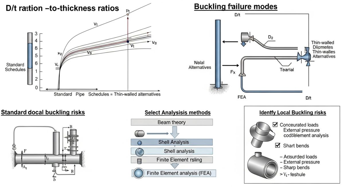
The primary concern with thin-walled pipe is local buckling under combined loading. While Caesar II is a beam-element-based solver, it does not inherently detect local shell buckling. To mitigate this, I perform a secondary check using the ASME Boiler and Pressure Vessel Code (BPVC) Section VIII, Division 2, Part 5, which provides more robust criteria for buckling than the standard B31.3 piping code.
Field Warning: The Buckling Trap
Never assume that a “pass” in Caesar II implies structural integrity for thin-walled pipe. The software checks for longitudinal stress and displacement, but it does not evaluate the shell’s resistance to ovalization. In large-diameter, thin-walled lines, the pipe can ovalize under bending moments, which drastically reduces the moment of inertia and leads to premature collapse.
To calculate the critical buckling pressure or moment, I often use the following approach: First, determine the effective section modulus by accounting for the reduced wall thickness. Second, apply the ASME B31.3 pressure design thickness (t) calculation, ensuring that the corrosion allowance is not neglected. If the D/t ratio is high, the pressure-stiffening effect can actually help prevent buckling, but this is highly dependent on the internal pressure being maintained.
In my experience, the most common error is failing to model the branch connections correctly. For thin-walled headers, the reinforcement pads or weldolets must be modeled with appropriate SIFs. If the header is thin, the branch connection is a high-stress concentration zone that can trigger a local failure long before the rest of the line reaches its allowable stress limit.
Thin-Walled Analysis Trade-offs: Evaluating the benefits of using Caesar II for thin-walled systems versus the inherent limitations of beam-element modeling in high D/t ratio scenarios.
Advantages
- Rapid iteration of support locations for large-bore systems.
- Seamless integration with ASME B31.3 stress reporting.
- Efficient handling of thermal expansion loads in complex layouts.
- Standardized SIF library reduces manual calculation errors.
- Ability to perform non-linear analysis for gaps and friction.
Disadvantages
- Beam elements fail to capture local shell ovalization.
- Default SIFs may be non-conservative for high D/t ratios.
- Cannot predict local buckling without external FEA validation.
- Sensitivity to mesh density in non-linear modeling.
- Requires manual intervention for thin-walled flexibility factors.
Thin-Walled Piping Implementation: Critical industrial sectors where high D/t ratio piping requires precise stress analysis to ensure operational safety and structural longevity.
Large-Diameter Cooling Water Systems
In power generation plants, cooling water lines often feature D/t ratios exceeding 100 due to the massive flow requirements. Caesar II is used here to manage the significant thermal expansion and weight loads, while manual checks ensure the thin walls do not collapse under vacuum conditions or water hammer events.
Low-Pressure Gas Transmission Headers
Gas processing facilities utilize large-diameter headers to minimize pressure drop. These lines are highly susceptible to wind-induced vibration and seismic loads, requiring a rigorous Caesar II model that accounts for the reduced stiffness of the thin-walled pipe sections.
Atmospheric Storage Tank Piping
Piping connected to large storage tanks often involves thin-walled sections to accommodate settlement and thermal movement. The analysis must focus on the nozzle loads imposed on the tank shell, where the thin-walled pipe acts as a flexible link to prevent tank wall deformation.
HVAC and Ducting Systems
While often considered secondary, large-bore HVAC ducting in industrial facilities requires stress analysis to prevent fatigue failure. Using Caesar II allows engineers to model these thin-walled structures as equivalent piping systems to ensure they can withstand operational vibrations and thermal cycling.
When performing a ASME B31.3 stress analysis for thin-walled piping where the diameter-to-thickness (D/t) ratio exceeds 100, the standard flexibility factors often become non-conservative. In my experience, the primary challenge lies in the rapid ovalization of the pipe cross-section under bending moments, which significantly reduces the effective stiffness of the piping system compared to standard schedule pipe.
The following table outlines the critical parameters that must be manually adjusted or verified within the Caesar II software environment. While the software calculates standard SIFs based on nominal dimensions, users must manually override these values when the D/t ratio enters the thin-walled regime to account for the increased susceptibility to local buckling and excessive deformation.
| Parameter | Standard Limit | Thin-Walled Adjustment |
|---|---|---|
| Flexibility Factor (k) | 1.65 / h | Apply correction for ovalization |
| SIF (In-Plane) | 0.9 / h^(2/3) | Increase based on D/t > 100 |
| Buckling Limit | Yield Strength | Use critical buckling pressure |
Always ensure that the “Thin-Walled” flag is enabled in the Caesar II element input sheet. Failure to do so will result in the software utilizing thick-walled equations that underestimate the flexibility and overestimate the structural integrity of the line.
The following matrix maps the core technical entities required for high-fidelity stress analysis in Caesar II. When dealing with thin-walled piping, the interaction between internal pressure and external bending moments becomes the governing failure mode, necessitating a departure from standard design assumptions.
Engineers must cross-reference these entities against the specific project piping specifications. Note that the “Flexibility Characteristic” (h) is the most sensitive variable in this matrix; even minor deviations in wall thickness due to corrosion allowance or manufacturing tolerances can lead to significant shifts in the calculated stress range.
| Entity | Acronym | Standard Reference |
|---|---|---|
| Stress Intensification Factor | SIF | ASME B31.3 |
| Flexibility Characteristic | h | ASME B31.3 |
| Diameter to Thickness | D/t | API 5L / ASME |
By maintaining this mapping, you ensure that the Caesar II model remains grounded in physical reality. Always verify that the software’s internal database matches the actual pipe material properties, especially when dealing with non-standard alloys or high-temperature applications where the modulus of elasticity varies significantly.
Verifying the integrity of thin-walled piping systems requires a rigorous approach that extends beyond the computer model. In my field experience, the most common failures occur not due to calculation errors, but due to discrepancies between the “as-designed” model and the “as-built” reality of the site installation.
-
1.
Confirm actual wall thickness measurements via ultrasonic testing (UT) to account for manufacturing tolerances. -
2.
Validate that all support locations match the Caesar II model coordinates within a 5mm tolerance. -
3.
Inspect for local dents or ovality in pipe sections, as these act as stress risers in thin-walled lines. -
4.
Verify that the insulation weight is correctly modeled, as thin-walled pipe is highly sensitive to dead-weight deflection. -
5.
Check for proper alignment of expansion joints to prevent unintended bending moments on thin-walled segments.
Before finalizing your stress report, ensure that the “As-Built” data has been imported into the Caesar II input file. If the field measurements indicate a wall thickness lower than the nominal value, you must re-run the analysis to ensure the D/t ratio remains within the safe operating envelope defined by ASME B31.3. Neglecting these site-specific variables is the primary cause of premature buckling in large-diameter, thin-walled ducting and piping systems.
Field Case Study: Real-World Application
Problem: Unexpected Buckling in Large Diameter Header
A large-diameter, thin-walled process header experienced localized buckling during a thermal transient event.
- D/t ratio exceeded 120, making the pipe highly susceptible to ovalization.
- The original Caesar II model used standard SIFs, failing to account for the increased flexibility.
- Thermal expansion was constrained by rigid supports that did not allow for pipe rotation.
- Internal pressure was insufficient to provide the necessary hoop stress to resist buckling.
Outcome: Successful Mitigation and System Stabilization
The system was successfully remediated by implementing a revised stress analysis strategy.
- Updated the Caesar II model with custom SIFs derived from thin-walled shell theory.
- Replaced rigid supports with spring hangers to accommodate thermal growth.
- Installed stiffening rings at critical high-stress locations to prevent cross-sectional deformation.
- Achieved full compliance with ASME B31.3 standards for the revised operating conditions.
My recommendation for similar projects is to always perform a sensitivity analysis on the D/t ratio. If your model shows high stress at a junction, do not rely on default software settings; manually verify the flexibility characteristic and consider the impact of local ovalization on the overall system stiffness.
Frequently Asked Engineering Questions
Why does D/t ratio impact Caesar II results?
How do I calculate the flexibility factor manually?
What is the buckling limit for thin-walled pipe?
Can I use standard SIFs for thin-walled pipe?
How does internal pressure affect stress analysis?
What is the role of stiffening rings?
📚 Recommended Resources: Caesar II stress analysis
Read these Guides
🎓 Advanced Training



Complete Course on
Piping Engineering
Check Now
Key Features
- 125+ Hours Content
- 500+ Recorded Lectures
- 20+ Years Exp.
- Lifetime Access
Coverage
- Codes & Standards
- Layouts & Design
- Material Eng.
- Stress Analysis
