Table of Contents
Mastering Caesar II Load Cases for Pipe Stress Analysis
In my 20 years of piping engineering, I have reviewed hundreds of stress models. If there is one place where junior stress analysts consistently stumble, it is in the configuration of the load case editor. A single misconfigured load case can mask a catastrophic flange leak, hide a massive nozzle overload, or fail to show a pipe lifting off its support.
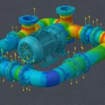
When we design piping systems for high-temperature refineries or high-pressure steam plants, we are not just drawing lines in a 3D space. We are managing energy. Caesar II is the industry-standard tool that helps us simulate how this energy behaves. However, the software is only as smart as the load cases you feed it. If you do not set up your sustained, expansion, and operational cases to reflect physical reality, your stress reports are nothing more than expensive guesswork.
What You Will Learn in This Guide
- The exact mathematical difference between algebraic and independent load cases.
- How to configure non-linear load cases to capture friction and support lift-off.
- Step-by-step setup for sustained, expansion, and occasional load cases under ASME B31.3.
How to Configure Caesar II Load Cases Correctly
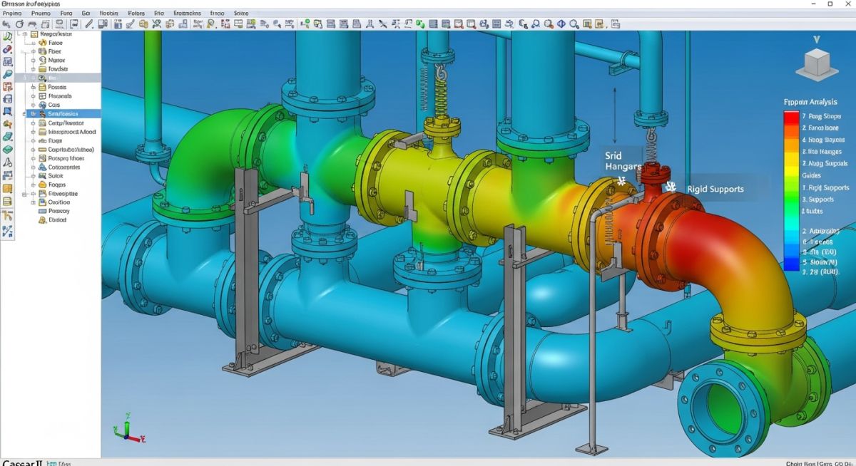
To build an accurate stress model, you must understand how Caesar II processes loads. The software uses individual load components—such as Weight (W), Thermal displacement (T), Pressure (P), and Occasional forces (U)—and combines them into specific load cases.
The Three Primary Stress Categories
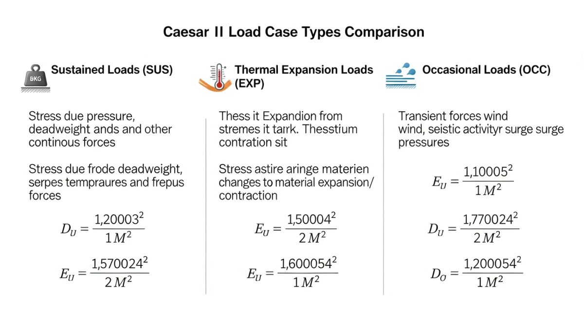
Every piping code divides stresses into three main categories. Your load cases must target these specifically:
- Sustained Stresses (SUS): Caused by gravity and pressure. These are non-self-limiting loads. If the material yields, the load keeps pushing until failure occurs.
- Expansion Stresses (EXP): Caused by thermal expansion and displacement. These are self-limiting. Once the pipe expands or deforms, the stress is relieved.
- Occasional Stresses (OCC): Caused by wind, seismic events, relief valve thrust, or water hammer. These are short-duration loads.
The Mathematics of Non-Linear Load Cases
In a perfectly linear system, the stress caused by thermal expansion is independent of weight. However, real-world piping systems are highly non-linear. Friction on support steel, guide gaps, and spring hangers introduce non-linearities.
For example, when a pipe heats up, it may lift off a support. When it lifts off, the weight that was on that support is transferred to adjacent supports. This changes the sustained stress profile of the system in its operating state. To capture this, Caesar II uses the following logic:
Case 2 (SUS): W + P1 (Sustained Case)
Case 3 (EXP): L1 – L2 (Expansion Case, calculated as Operating minus Sustained)
By subtracting the Sustained case (L2) from the Operating case (L1), Caesar II calculates the true expansion stress range (L3) while preserving the non-linear boundary conditions. If you simply ran a case with “T1” alone, the software would assume all supports remain in contact, leading to highly inaccurate force and stress calculations.
Calculating Stress Ranges
The expansion stress range is evaluated against the allowable displacement stress range (SA), which is calculated using the formula:
SA = f * (1.25 * Sc + 0.25 * Sh)
Where “Sc” is the basic allowable stress of the material at the minimum metal temperature, “Sh” is the basic allowable stress at the maximum metal temperature, and “f” is the stress range reduction factor. If your sustained stresses are low, you can also take advantage of the “liberal allowable” stress range, which adds the unused portion of the sustained allowable stress to SA.
Standard Caesar II Load Case Templates
Below is the standard load case configuration template that I recommend for a typical high-temperature piping system with one thermal operating condition and one design pressure. This setup complies fully with ASME B31.3.
| Case No. | Combination / Load Components | Stress Type | Description / Purpose |
|---|---|---|---|
| L1 | W + P1 + T1 | OPE (Operating) | Calculates operating displacements, forces, and nozzle loads. |
| L2 | W + P1 | SUS (Sustained) | Calculates sustained stresses to verify gravity and pressure limits. |
| L3 | L1 – L2 | EXP (Expansion) | Algebraic difference case to find the true thermal stress range. |
| L4 | W + P1 + T1 + U1 | OPE (Operating) | Operating case including occasional load (e.g., wind or seismic). |
| L5 | L4 – L1 | OCC (Occasional) | Isolates the occasional stress component for code compliance. |
Technical Mapping & Specifications Matrix
To ensure your model aligns with international standards, use this mapping matrix to link physical parameters to Caesar II variables and code references.
| Physical Parameter | Caesar II Variable | Primary Code Reference | Acceptance Criteria |
|---|---|---|---|
| Piping Deadweight | W (Weight) | ASME B31.3 Clause 302.3.5 | Sustained allowable stress (Sh) |
| Internal Design Pressure | P1 (Pressure) | ASME B31.3 Clause 304 | Minimum wall thickness verification |
| Thermal Expansion | T1 (Temperature) | ASME B31.3 Clause 319 | Displacement stress range (SA) |
| Wind / Seismic Loads | WIN / U1 (Occasional) | ASCE 7 / IBC | 1.33 times hot allowable stress (Sh) |
Why Caesar II Load Cases Prevent Piping Failures
Before you issue a stress report for construction, you must verify that your Caesar II model matches the physical reality of the field. In my experience, many field failures occur because the stress analyst assumed “ideal” conditions that do not exist on the construction site.
Pre-Construction Stress Model Checklist
-
Friction Coefficients: Ensure steel-on-steel supports have a friction coefficient (mu) of 0.3 modeled. Do not leave friction at 0 unless using low-friction PTFE slide plates (mu = 0.1).
-
Spring Hanger Pre-loads: Verify that spring hanger selections are locked in the sustained case and allowed to travel in the operating case.
-
Flange Leakage Cases: Configure dedicated pressure-only and operating-only cases to run flange leakage checks per ASME Section VIII Division 1 Appendix 2 or the NC 3650 method.
-
Expansion Joint Stiffness: Double-check that bellows and expansion joints have their axial, lateral, and angular stiffness values entered per the manufacturer’s datasheet.
-
Occasional Load Factors: Ensure wind and seismic static seismic g-factors are calculated using ASCE 7 guidelines and mapped to the correct occasional load cases.
Field Case Study: Real-World Application
The Problem: Turbine Nozzle Overload
During commissioning of a 12-inch high-pressure steam line (operating at 350°C and 40 bar), the steam turbine experienced severe casing vibration. The maintenance team discovered that the turbine nozzle was subjected to forces far exceeding the allowable limits specified by API 617.
The original stress analysis report showed all nozzle loads were within limits. Upon reviewing the Caesar II model, I discovered that the analyst had modeled the system using linear thermal expansion without accounting for friction (mu = 0) and support lift-off. They had also used a simple thermal-only case (T1) to evaluate expansion stresses, which completely missed the non-linear behavior of the piping system.
The Outcome: Corrective Modeling and Redesign
I rebuilt the Caesar II model using the correct algebraic difference method: L1 (W+P1+T1), L2 (W+P1), and L3 (L1-L2) with a realistic friction coefficient of 0.3 on all steel-on-steel supports.
The corrected model revealed that the pipe lifted off three consecutive spring hangers during operation. This transferred excessive deadweight directly to the turbine nozzle. To resolve this, we redesigned the support configuration by replacing two rigid supports with variable spring hangers and adjusting the pre-loads.
The new Caesar II run showed nozzle loads dropped by 65%, bringing them well within API 617 limits. The physical modifications were implemented on-site, and the turbine has run smoothly ever since.
Frequently Asked Engineering Questions
What is the difference between algebraic and utility load cases in Caesar II?
Why must we use the operating case to calculate expansion stress range?
How do you handle friction in Caesar II load cases?
What is a “cold spring” load case and how is it modeled?
How does Caesar II calculate flange leakage using load cases?
When should occasional load cases include wind or seismic forces?
Complete Course on
Piping Engineering
Check Now
Key Features
- 125+ Hours Content
- 500+ Recorded Lectures
- 20+ Years Exp.
- Lifetime Access
Coverage
- Codes & Standards
- Layouts & Design
- Material Eng.
- Stress Analysis

Related posts:
![Close-up of a composite-wrapped pipeline on an offshore oil rig showing woven fiber texture.]()
How Anti-Corrosive Composites Protect Critical Oil and Gas Assets
![Infographic flowchart of the GRP GRE FRP piping stress analysis workflow in START-PROF.]()
Rigid Struts: Definition, Applications, and Modeling in Caesar II
![3D stress analysis model of GRP piping system in START-PROF software showing stress distribution.]()
Stress Analysis of GRP / GRE / FRP Piping using START-PROF
![Industrial centrifugal pump installed on a concrete foundation with precision piping and alignment.]()
How to Use a Pump Installation Checklist for Maximum Reliability
![3D Caesar II pipe stress analysis model of a centrifugal pump piping system showing stress distribution.]()
Pump-Piping Alignment Caesar II Stress Analysis Methodology
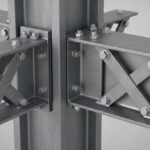
![3D render of a structural steel cross-bracing connection with a gusset plate.]()
Mastering Steel Connections with a Cross-Bracing Design Example