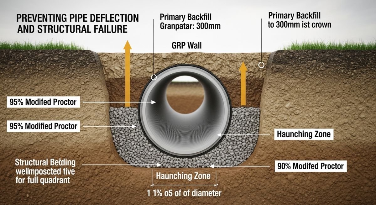
Buried GRP/FRP Pipe Laying and Installation Procedure
In my two decades of managing large-scale industrial piping projects, I have observed that the failure of buried GRP (Glass Reinforced Plastic) or FRP (Fiberglass Reinforced Plastic) systems is rarely due to the pipe material itself. Instead, it almost always stems from a breakdown in the installation procedure. Unlike rigid steel or concrete piping, GRP is a flexible conduit that relies entirely on the surrounding soil envelope to maintain its shape and resist external hydrostatic and earth loads.
If you neglect the compaction density of the side-fill or fail to account for the native soil modulus, you are essentially inviting deflection-related fatigue. This guide breaks down the critical technical requirements for trenching, bedding, and backfilling to ensure your pipeline meets its design life. We will focus on the interaction between the pipe stiffness and the soil-pipe system, ensuring you avoid common pitfalls that lead to buckling or joint leakage.
Key Takeaways for Field Engineers
- Always verify the soil modulus (E’) against the pipe stiffness class (SN) before excavation.
- Ensure the haunching zone is fully compacted to prevent pipe “egging” or vertical deflection.
- Maintain strict adherence to the minimum cover requirements to prevent live-load crushing.
- Use only specified granular materials for the pipe embedment zone to ensure uniform support.
Technical Deep-Dive: Buried GRP/FRP Pipe Laying and Installation Procedure
Structural Pipe-Soil Interaction: The fundamental design principle for buried GRP/FRP piping is the reliance on the soil envelope to provide lateral support, which prevents the pipe from exceeding its allowable deflection limits, typically capped at 5% of the internal diameter per ASTM D3839.
When installing GRP pipe, the trench width must be sufficient to allow for proper compaction equipment access. If the trench is too narrow, you cannot achieve the required Proctor density in the haunching area—the space beneath the pipe’s springline. In my experience, this is the most common site error. Without proper haunching, the pipe loses its lateral support, leading to excessive vertical deflection and potential buckling under soil overburden.

Calculating Soil-Pipe Stiffness
The performance of the system is governed by the Iowa Formula, which relates the pipe deflection to the pipe stiffness (PS) and the soil modulus (E’). The total deflection is calculated as:
Deflection = (K * W * r^3) / (EI + 0.061 * E’ * r^3)
Where K is the bedding constant, W is the load per unit length, r is the pipe radius, E is the modulus of elasticity of the pipe material, and I is the moment of inertia of the pipe wall. As an engineer, you must ensure that the E’ value of your backfill material is consistent with the design assumptions. If your design assumes a Class I material (crushed stone) but the contractor uses native silty soil, the E’ value drops significantly, causing the denominator to shrink and the deflection to spike.
Field Warning: The Danger of Point Loading
Never allow the pipe to rest on rocks or hard protrusions in the trench bottom. This creates a “beam effect” where the pipe is supported at a single point, leading to localized stress concentrations that exceed the material’s strain capacity. Always provide a minimum of 150mm of bedding material, even in stable soil conditions.
For deep burials, the hydrostatic pressure of the groundwater must also be considered. GRP pipe is susceptible to buckling if the external pressure exceeds the critical buckling pressure. This is defined by the Luscher equation, which accounts for the pipe stiffness and the soil modulus. If the groundwater table is high, you must use a higher stiffness class (e.g., SN 5000 or SN 10000) and ensure the backfill is free-draining to prevent pore pressure buildup against the pipe wall.
GRP Installation Performance: The selection of GRP/FRP for buried applications involves balancing its superior corrosion resistance against the stringent requirements for soil-structure interaction and compaction control.
Advantages
- Exceptional resistance to aggressive soil chemistry and stray electrical currents.
- High strength-to-weight ratio simplifies handling and reduces heavy equipment requirements.
- Smooth internal surface (Hazen-Williams C=150) minimizes pumping energy costs over time.
- Flexible nature allows for minor ground settlement without catastrophic joint failure.
- Long service life in corrosive environments compared to carbon steel or ductile iron.
Disadvantages
- High sensitivity to improper compaction and poor trench bottom preparation.
- Requires specialized training for field jointing and adhesive curing processes.
- Susceptible to buckling under high external hydrostatic loads if not properly stiffened.
- Lower impact resistance during installation compared to metallic piping systems.
- Strict adherence to deflection monitoring is mandatory during the backfilling phase.
Industrial Pipeline Deployment: GRP/FRP piping systems are deployed across diverse sectors where chemical inertness and structural flexibility are required for long-term buried service.
Desalination Intake and Outfall Lines
Large diameter GRP pipes are the industry standard for seawater intake and brine discharge due to their immunity to chloride-induced corrosion. The installation requires precise underwater or coastal trenching to ensure the pipe remains stable against tidal forces and shifting seabed sediments.
Municipal Wastewater Collection Systems
In urban environments, GRP is used for gravity sewer mains where hydrogen sulfide gas would rapidly degrade concrete or metallic pipes. The installation procedure focuses on achieving high-density compaction in the haunching zone to prevent long-term deflection under heavy traffic loads.
Chemical Processing Plant Effluent Lines
Industrial facilities utilize GRP for buried effluent lines carrying acidic or caustic waste streams that would compromise traditional piping materials. These installations often involve complex routing through congested plant areas, requiring careful management of trench shoring and backfill material selection.
District Cooling and Chilled Water Networks
GRP piping is increasingly used for buried district cooling networks due to its low thermal conductivity and ease of installation in long, straight runs. The procedure emphasizes thermal expansion management and the use of thrust blocks at changes in direction to maintain system integrity.
When executing a Buried GRP/FRP pipe Laying and Installation Procedure, the structural performance of the conduit is intrinsically linked to the quality of the surrounding soil envelope. Unlike rigid materials like concrete, GRP/FRP pipes are flexible conduits that rely on the passive resistance of the sidefill to prevent excessive deflection under earth and live loads. The following table outlines the minimum requirements for bedding and backfill materials as defined by AWWA M45 and ASTM D3839.
Engineers must ensure that the modulus of soil reaction (E’) is calculated based on the specific compaction density achieved in the field. Failure to meet these classification standards often leads to localized buckling or ovalization beyond the allowable 5% limit. Always verify that the native soil is not expansive or highly organic, as these materials provide insufficient lateral support for long-term structural stability.
| Soil Class | Description | Compaction Level | E’ (psi) |
|---|---|---|---|
| Class I | Crushed stone, angular particles | Dumped/Lightly vibrated | 3000 |
| Class II | Coarse sands and gravels | 90-95% Standard Proctor | 1000-2000 |
| Class III | Fine sands, silty gravels | 90-95% Standard Proctor | 400-1000 |
The following matrix correlates the critical engineering entities involved in the Buried GRP/FRP pipe Laying and Installation Procedure with their respective governing standards and physical parameters. This mapping is essential for quality assurance during the procurement and construction phases of large-scale industrial piping projects.
By aligning these entities, project managers can ensure that the design assumptions—such as pipe stiffness (SN) and burial depth—are correctly translated into site-specific installation instructions. Each entity listed below represents a critical control point where deviation from the specification can compromise the structural integrity of the entire pipeline system.
| Entity | Standard | Parameter |
|---|---|---|
| Pipe Stiffness | ASTM D2412 | N/mm2 (SN) |
| Deflection Limit | AWWA M45 | Percentage of Diameter |
| Bedding Modulus | ASTM D3839 | E’ (psi or MPa) |
Successful implementation of a Buried GRP/FRP pipe Laying and Installation Procedure requires rigorous site verification. Before any pipe section is lowered into the trench, the installation team must validate the trench geometry, bedding material quality, and the absence of point loads that could cause stress concentrations in the composite wall.
- 1. Trench Width Verification: Ensure the trench width at the pipe springline is sufficient for proper compaction equipment access per ASTM D3839.
- 2. Bedding Uniformity: Confirm the bedding material is free of large rocks or debris that could create point loads on the pipe invert.
- 3. Joint Integrity: Inspect all spigot and bell ends for damage before lubrication and assembly to prevent leakage under hydrostatic testing.
- 4. Initial Backfill: Verify that the haunching material is placed and compacted manually to eliminate voids beneath the pipe springline.
- 5. Deflection Monitoring: Perform a mandrel test or laser measurement after the initial 300mm of cover is placed to ensure deflection remains within the 5% design limit.
These checkpoints are not merely administrative; they are critical engineering safeguards. In my experience, the most common cause of GRP pipeline failure is the presence of voids in the haunching zone, which leads to uneven load distribution and eventual structural cracking. Always document the compaction test results for every 100 meters of pipe installed to maintain a robust quality management record.
Field Case Study: Real-World Application
Problem: Excessive Deflection in High-Water-Table Trenching
- Inadequate dewatering led to saturated, unstable trench bottom conditions.
- Use of non-specified native silty soil for haunching resulted in poor compaction.
- Pipe deflection exceeded 8% within 48 hours of backfilling.
- Lack of proper bedding material caused localized stress concentrations at the pipe invert.
Outcome: Remediation and Structural Stabilization
- Implemented a well-point dewatering system to lower the water table by 1.5 meters.
- Replaced native soil with Class I crushed stone to provide a stable, self-compacting foundation.
- Achieved a final deflection of 2.2%, well within the 5% design threshold.
- Established a mandatory daily inspection protocol for all future trenching operations.
The recommendation for similar projects is to prioritize geotechnical site investigation. If the water table is high, do not attempt to use native soil for the pipe envelope. The cost of importing high-quality granular bedding is negligible compared to the expense of excavating and replacing a failed pipeline section.
Frequently Asked Engineering Questions
What is the maximum allowable deflection for GRP pipe?
According to AWWA M45, the standard long-term deflection limit for GRP pipe is typically set at 5% of the internal diameter. This limit ensures that the pipe maintains its structural shape and prevents the initiation of micro-cracking in the resin matrix.
- Initial deflection during installation should be monitored to ensure it does not exceed 3%.
- Long-term deflection accounts for soil consolidation and creep over the design life.
- Always consult the specific manufacturer’s data sheet, as some high-stiffness pipes may allow for different limits.
Why is haunching critical for GRP pipe installation?
The haunching zone, located between the trench bottom and the pipe springline, is the most critical area for structural support. Because GRP is a flexible conduit, it relies on the passive soil pressure in this zone to resist vertical loads.
- Voids in the haunching area lead to uneven support and potential pipe wall buckling.
- Manual compaction is required in this zone to ensure the material is fully integrated with the pipe curvature.
- Proper haunching prevents the pipe from acting as a beam, which it is not designed to do.
How does soil type affect the modulus of soil reaction?
The modulus of soil reaction (E’) is a measure of the soil’s ability to resist pipe deflection. Different soil classifications provide varying levels of support, which directly impacts the required pipe stiffness.
- Class I materials (crushed stone) provide the highest E’ values due to their angularity and self-compacting nature.
- Class IV and V soils (silts and clays) are generally unsuitable for pipe bedding as they are prone to moisture-related volume changes.
- Engineers must use the ASTM D3839 tables to select the appropriate E’ value based on the compaction density achieved.
Can I use native soil for backfilling GRP pipes?
Using native soil is only permissible if it meets the classification requirements for Class II or Class III materials. If the native soil is highly organic, expansive, or contains large rocks, it must be replaced with imported granular material.
- Native soil must be tested for moisture content and gradation before being approved for use.
- If the native soil cannot be compacted to the required 90-95% Standard Proctor density, it should not be used in the pipe zone.
- Always prioritize the use of imported, well-graded granular material to ensure consistent structural performance.
What is the purpose of a mandrel test?
A mandrel test is a physical verification method used to ensure that the installed pipe has not exceeded the allowable deflection limits. A rigid cylinder (mandrel) is pulled through the pipe; if it passes, the pipe is within the specified deflection tolerance.
- The mandrel diameter is typically set to 95% of the pipe’s internal diameter.
- This test should be performed at least 30 days after installation to allow for initial soil settlement.
- It provides a definitive, non-subjective pass/fail result for quality control inspectors.
How do I handle high groundwater during installation?
High groundwater is a significant risk factor that can lead to pipe flotation and soil instability. Effective dewatering is the only reliable way to manage this condition during the installation process.
- Use well-point systems or deep wells to lower the water table at least 0.5 meters below the trench bottom.
- Ensure the trench is kept dry until the pipe is fully covered with at least one pipe diameter of backfill.
- If dewatering is not feasible, consider using concrete ballast or anti-flotation measures to secure the pipe.
📚 Recommended Resources: Buried GRP
Read these Guides
🎥 Watch Tutorials

Complete Course on
Piping Engineering
Check Now
Key Features
- 125+ Hours Content
- 500+ Recorded Lectures
- 20+ Years Exp.
- Lifetime Access
Coverage
- Codes & Standards
- Layouts & Design
- Material Eng.
- Stress Analysis
