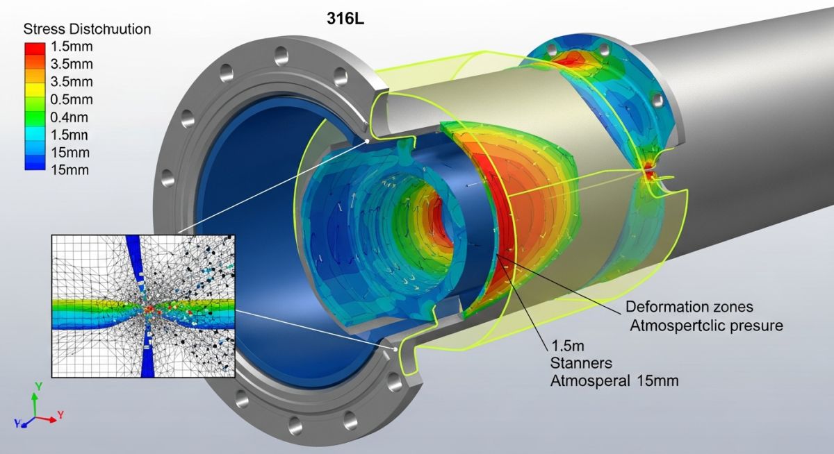
How to Perform the Buckling Analysis of Vacuum Piping
In my two decades of field experience, I have seen too many junior engineers treat vacuum systems as simple “negative pressure” lines. This is a dangerous oversight. When a pipe operates under vacuum, the external atmospheric pressure acts as a compressive force attempting to crush the pipe wall inward. Unlike internal pressure, which tends to stabilize a pipe, external pressure triggers instability modes that can lead to sudden, catastrophic structural collapse.
Performing a rigorous buckling analysis of vacuum piping is not merely a design preference; it is a mandatory safety requirement for any process system operating below atmospheric pressure. We must account for geometric imperfections, material stiffness, and the specific temperature-dependent properties of the alloy. This guide breaks down the complex mechanics of external pressure design to ensure your piping systems remain robust under the most demanding vacuum conditions.
Key Takeaways for Vacuum Design
- Understand the critical difference between hoop stress and buckling instability.
- Master the use of ASME BPVC Section VIII, Division 1, UG-28 for external pressure calculations.
- Identify the influence of L/Do (length-to-diameter) ratios on pipe wall thickness requirements.
- Learn how to apply stiffening rings to mitigate buckling without excessive wall thickness.
Technical Deep-Dive: Buckling Analysis of Vacuum Piping
External Pressure Design Principles: The buckling analysis of vacuum piping requires calculating the allowable external pressure (Pa) that a pipe can withstand before it undergoes elastic or inelastic instability. Under ASME B31.3, we refer to the methodology established in ASME BPVC Section VIII, Division 1, UG-28. The analysis is highly sensitive to the ratio of the outside diameter (Do) to the wall thickness (t), as well as the unsupported length (L) of the pipe section.
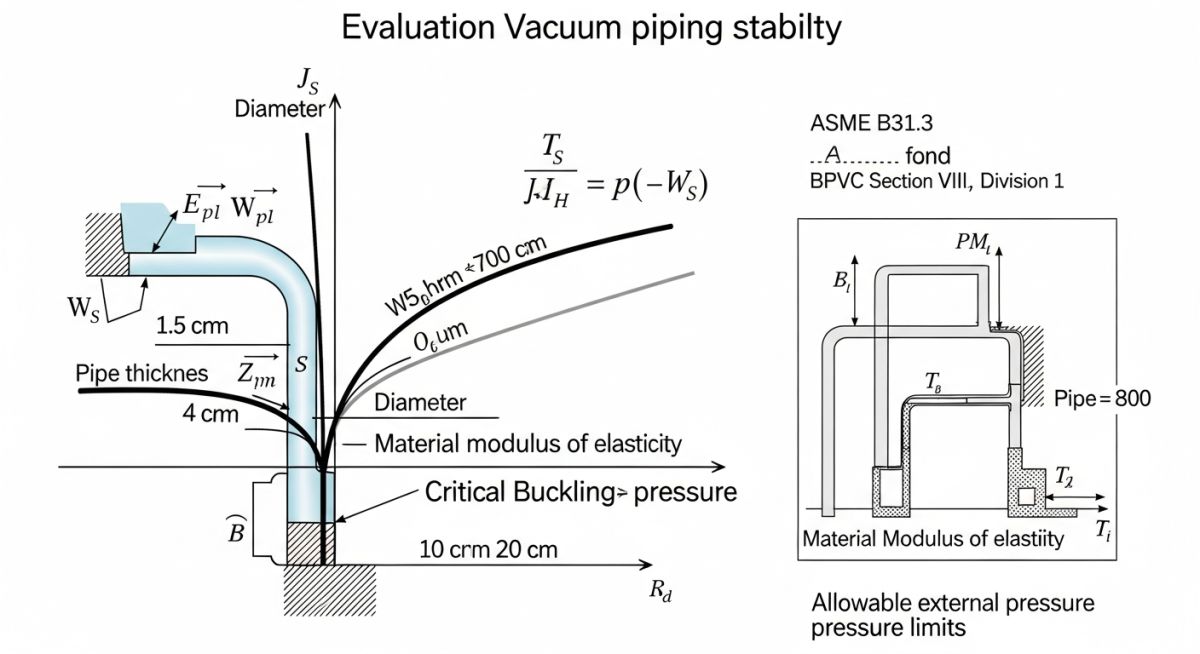
To begin the calculation, we first determine the factor A, which represents the geometric factor. This is calculated as A = 0.125 / (Do/t). Once A is determined, we enter the material-specific stress-strain charts provided in the ASME code. These charts account for the modulus of elasticity (E) at the design temperature. If the calculated A value falls to the left of the material curve, the failure mode is elastic; if it falls to the right, it is plastic.
The next step involves calculating the factor B, which is derived from the material charts based on the value of A. The allowable external pressure (Pa) is then calculated using the formula: Pa = 4B / (3 * (Do/t)). This value must be greater than or equal to the design external pressure (typically 15 psi for full vacuum). If Pa is insufficient, you have three primary engineering levers: increase the wall thickness (t), reduce the unsupported length (L) by adding stiffening rings, or select a material with a higher modulus of elasticity at the operating temperature.
It is critical to note that vacuum piping often experiences thermal cycling. As the temperature increases, the modulus of elasticity (E) decreases, which directly reduces the buckling resistance of the pipe. Always perform your analysis at the maximum expected operating temperature to ensure the pipe does not collapse during a process upset or startup phase.
Vacuum System Design Trade-offs: Evaluating the structural implications of external pressure requires balancing material costs, fabrication complexity, and long-term operational safety under vacuum conditions.
Advantages
- Enhanced Structural Rigidity: Properly designed stiffening rings significantly increase the pipe’s resistance to ovalization.
- Standardized Compliance: Using ASME UG-28 provides a globally recognized, legally defensible design basis.
- Predictable Failure Modes: Rigorous analysis allows engineers to design for controlled deformation rather than catastrophic rupture.
- Material Optimization: Allows for thinner walls in long-span sections by utilizing strategic stiffening rather than uniform thickness increases.
Disadvantages
- Increased Fabrication Costs: Adding stiffening rings requires precise welding and NDT, increasing labor hours.
- Thermal Expansion Constraints: Stiffening rings can create localized stress concentrations during thermal expansion cycles.
- Weight Penalties: Heavier wall thicknesses required for vacuum resistance increase support load requirements.
- Complexity in Inspection: Stiffening rings can obstruct visual inspection and complicate external insulation installation.
Vacuum Piping Implementation Scenarios: The following sectors rely on precise buckling analysis to maintain the integrity of vacuum-rated process infrastructure.
Cryogenic Liquid Transfer
Vacuum-jacketed piping is essential for transporting liquefied gases like nitrogen or hydrogen. The inner pipe must withstand the external pressure of the vacuum annulus, requiring precise buckling calculations to prevent inner pipe collapse during cool-down cycles.
Vacuum Distillation Columns
In petrochemical refining, distillation under vacuum lowers boiling points to prevent thermal degradation of heavy hydrocarbons. The associated piping must be designed to handle full vacuum conditions, often requiring stiffening rings to manage the large diameters involved.
Semiconductor Gas Delivery
High-purity vacuum lines in semiconductor fabrication require extreme structural stability to prevent particulate generation. Buckling analysis ensures that even under high-vacuum conditions, the pipe geometry remains perfectly circular to maintain laminar flow and prevent turbulence.
Food and Beverage Dehydration
Vacuum drying systems for heat-sensitive food products utilize large-diameter piping to transport vapor. These systems operate under constant vacuum, necessitating rigorous buckling checks to ensure the thin-walled stainless steel piping does not buckle under atmospheric pressure.
When performing a buckling analysis of vacuum piping, engineers must strictly adhere to the external pressure design requirements outlined in ASME B31.3. The following table summarizes the critical geometric and material variables that dictate the allowable external pressure (Pa) before structural instability occurs. These parameters are derived from the Boiler and Pressure Vessel Code (BPVC) Section VIII, Division 1, which is referenced by B31.3 for vacuum-rated components.
It is vital to recognize that the interaction between the pipe diameter-to-thickness ratio and the modulus of elasticity is non-linear. As the vacuum level increases, the potential for elastic or inelastic buckling rises exponentially, necessitating precise wall thickness selection to maintain the integrity of the piping system under full vacuum conditions.
| Parameter | Symbol | Standard Reference |
|---|---|---|
| Outside Diameter | Do | ASME B31.3 Para 304.1.3 |
| Minimum Wall Thickness | t | ASME B31.3 Para 304.1.2 |
| Modulus of Elasticity | E | ASME BPVC Section II Part D |
| Poisson Ratio | v | ASME BPVC Section VIII Div 1 |
Engineers should ensure that the calculated allowable pressure exceeds the maximum vacuum pressure by a safety factor of at least 1.5, as recommended by industry best practices for critical process piping. Always verify that the material properties are evaluated at the maximum design temperature, as the modulus of elasticity degrades significantly under thermal load.
The following matrix maps the core technical entities involved in the buckling analysis of vacuum piping. Understanding these relationships is essential for maintaining compliance with international pressure vessel and piping standards. Each entity represents a specific physical constraint or material property that must be accounted for during the iterative design process.
By cross-referencing these entities with the appropriate ASME standards, designers can ensure that their vacuum piping systems are robust against collapse. This matrix serves as a foundational guide for junior and senior engineers alike when performing stress analysis or evaluating existing piping systems for vacuum service upgrades.
| Entity | Acronym | Standard |
|---|---|---|
| External Pressure | Pext | ASME BPVC VIII |
| Critical Buckling Pressure | Pcr | ASME B31.3 |
| Moment of Inertia | I | ASME B31.3 |
| Yield Strength | Sy | ASME II Part D |
Consistent application of these entities ensures that the piping system remains within the elastic region of the material stress-strain curve. If the calculated external pressure approaches the critical buckling pressure, the design must be revised to include stiffening rings or increased wall thickness to prevent catastrophic failure.
Vacuum System Integrity Verification: Before commissioning any piping system intended for vacuum service, a rigorous site verification process is mandatory. This checklist ensures that the physical installation aligns with the design calculations and that no hidden defects could lead to buckling under external pressure.
-
☐
Verify that the actual pipe wall thickness matches the design specification (ASME B31.3 Para 304.1.2). -
☐
Inspect for out-of-roundness (ovality) exceeding 1% of the nominal diameter, as this significantly reduces buckling resistance. -
☐
Confirm that all stiffening rings are welded according to the approved WPS and are free from undercut or porosity. -
☐
Perform a vacuum leak test to ensure the system maintains the required pressure differential without degradation. -
☐
Check for external mechanical damage or dents that could act as stress concentrators under external pressure.
During the site verification, pay close attention to the support spacing. Excessive spans between supports can lead to sagging, which introduces bending moments that interact negatively with the external pressure load. Always document the results of these checks in the project quality assurance log. If any deviation from the design is identified, a re-evaluation of the buckling analysis is required before the system is pressurized. Remember that vacuum systems are unforgiving; even minor geometric imperfections can lead to rapid, non-linear collapse if the external pressure exceeds the critical threshold defined by the ASME standards.
Problem: Unexpected Buckling in Vacuum Distillation Line
A 24-inch carbon steel vacuum distillation line experienced localized buckling during a routine process startup, leading to a complete system shutdown.
- The pipe wall thickness was reduced by 15% due to internal corrosion, which was not accounted for in the original buckling analysis.
- The operating temperature exceeded the design temperature, causing a reduction in the material modulus of elasticity.
- The vacuum pump reached a higher-than-expected vacuum level, exceeding the design pressure limit.
- The pipe ovality was measured at 2.5%, significantly higher than the allowable limit for vacuum service.
Outcome: Successful Remediation and System Upgrade
The system was restored to full operational capacity by implementing a comprehensive structural reinforcement strategy.
- Replaced the damaged pipe sections with a higher wall thickness schedule to compensate for potential future corrosion.
- Installed external stiffening rings at calculated intervals to increase the critical buckling pressure.
- Implemented a real-time vacuum monitoring system with automatic pressure relief valves to prevent over-vacuum conditions.
- Updated the maintenance protocol to include annual ultrasonic thickness measurements and ovality checks.
My recommendation for similar facilities is to always perform a sensitivity analysis on the buckling limit. By varying the wall thickness and ovality parameters in your calculations, you can identify the “tipping point” of your system before it becomes a field failure. Proactive monitoring is the only way to ensure long-term reliability in vacuum service.
Frequently Asked Engineering Questions
How does ovality affect the buckling limit?
- Higher ovality leads to earlier onset of plastic instability.
- ASME B31.3 and BPVC Section VIII provide specific charts that account for these imperfections.
- Even a 1% deviation from circularity can reduce the buckling capacity by over 20% in thin-walled pipes.
Why is temperature critical for vacuum buckling?
- Always use the modulus of elasticity value corresponding to the maximum design temperature.
- Failure to account for thermal degradation often leads to under-designing the wall thickness.
- Refer to ASME BPVC Section II Part D for temperature-corrected material properties.
What is the role of stiffening rings?
- They must be designed to resist the collapse pressure of the pipe section.
- Welding requirements for these rings are stringent to ensure load transfer.
- They are the most cost-effective solution for upgrading existing systems to handle higher vacuum levels.
How do I calculate the safety factor?
- Calculate the theoretical buckling pressure using the geometry and material properties.
- Divide this value by the operating vacuum pressure.
- If the result is below 1.5, the design is considered unsafe for long-term operation.
Can I use standard pipe schedules for vacuum?
- Always perform a buckling check for any pipe diameter exceeding 12 inches.
- Standard schedules may not provide enough stiffness for large-diameter vacuum headers.
- Custom wall thicknesses or stiffening rings are often required for large-scale vacuum systems.
What is the impact of corrosion on buckling?
- Include a corrosion allowance in your initial design calculations.
- Regular ultrasonic testing is required to monitor wall loss over time.
- If the wall thickness drops below the minimum required for buckling, the pipe must be replaced or reinforced immediately.
📚 Recommended Resources: buckling analysis of vacuum piping
Complete Course on
Piping Engineering
Check Now
Key Features
- 125+ Hours Content
- 500+ Recorded Lectures
- 20+ Years Exp.
- Lifetime Access
Coverage
- Codes & Standards
- Layouts & Design
- Material Eng.
- Stress Analysis
