
Battery Energy Storage Systems for Wind Projects: A Technical Guide
In my two decades of experience within the energy sector, I have observed that the primary challenge of wind energy is not the generation itself, but the variability of the resource. Integrating Battery Energy Storage Systems (BESS) into wind projects is no longer an optional luxury; it is a fundamental requirement for modern grid stability.
When we look at the physics of wind power, we are dealing with stochastic inputs that can fluctuate in seconds. By coupling these assets with high-density lithium-ion storage, we can effectively “smooth” the power output, transforming a volatile source into a dispatchable asset. This guide explores the engineering mechanics, the control logic, and the economic drivers that make BESS the backbone of the next generation of renewable energy infrastructure.
Key Takeaways for Engineers
- BESS enables frequency regulation and ramp-rate control for wind farms.
- Energy arbitrage allows operators to shift generation to high-demand periods.
- Compliance with IEEE 1547 and NERC standards is mandatory for grid interconnection.
- Thermal management and fire suppression are critical design parameters for BESS containers.
Battery Energy Storage Systems (BESS) Fundamentals and Integration
BESS Technical Architecture: The systematic application of electrochemical energy storage units coupled with bidirectional power conversion systems to manage the active and reactive power output of wind-based generation assets.
At the heart of any BESS-wind integration is the Power Conversion System (PCS). Unlike traditional static loads, the PCS must handle bidirectional power flow, allowing the battery to charge during periods of high wind and low grid demand, and discharge when the wind drops or prices peak. The efficiency of this conversion is governed by the IEC 62477 standard, which dictates the safety and performance requirements for power electronic converter systems.
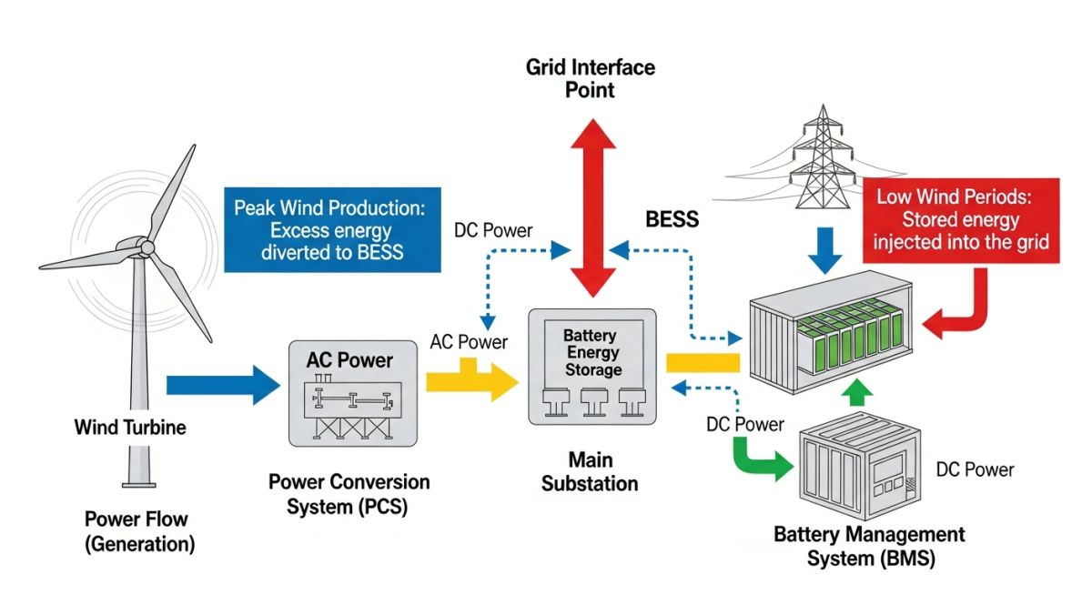
Control Logic and Ramp-Rate Mitigation
Wind turbines often exhibit rapid power fluctuations due to turbulence or gust events. To mitigate this, the BESS controller monitors the wind farm’s net output at the Point of Interconnection (POI). If the ramp rate exceeds the grid operator’s limit (e.g., 10% of nameplate capacity per minute), the BESS controller triggers an injection or absorption of power.
The calculation for the required BESS power capacity (P_bess) is defined by the difference between the actual wind power (P_wind) and the target ramp-limited power (P_target):
This calculation must be performed in real-time, typically with a latency of less than 100 milliseconds. Failure to maintain this response time can lead to grid instability and potential penalties from the Transmission System Operator (TSO).
Field Warning: Thermal Runaway Risks
In my experience, the most significant risk in BESS design is thermal runaway. Lithium-ion cells are sensitive to ambient temperature and charge/discharge cycles. You must ensure that the HVAC system is sized for the maximum heat rejection rate during peak discharge, adhering to NFPA 855 standards for the installation of stationary energy storage systems.
Energy Arbitrage and Capacity Firming
Beyond stabilization, BESS provides a mechanism for energy arbitrage. By storing energy when the Locational Marginal Price (LMP) is negative or low, and discharging when prices are high, the project improves its Internal Rate of Return (IRR). This requires a sophisticated Battery Management System (BMS) that tracks the State of Health (SoH) and State of Charge (SoC) to prevent premature degradation of the battery cells.
BESS Operational Trade-offs: A critical evaluation of the performance benefits versus the lifecycle costs and safety requirements inherent in utility-scale battery deployment.
Advantages
- Enhanced Grid Reliability: Provides synthetic inertia and frequency response, essential for high-penetration renewable grids.
- Revenue Diversification: Enables participation in ancillary service markets, such as spinning reserves and frequency regulation.
- Curtailment Reduction: Captures excess energy that would otherwise be wasted during grid congestion events.
- Ramp-Rate Control: Smooths out wind power volatility, ensuring compliance with strict TSO interconnection agreements.
Disadvantages
- High Capital Expenditure: Significant upfront costs for battery modules, inverters, and fire suppression systems.
- Degradation Cycles: Battery capacity fades over time, necessitating augmentation or replacement strategies after 7-10 years.
- Safety and Regulatory Burden: Stringent compliance with fire codes and environmental regulations increases project complexity.
- Thermal Management Complexity: Requires robust HVAC and liquid cooling systems to prevent cell failure in extreme climates.
Strategic BESS Deployment: Targeted use cases for battery storage systems to solve specific grid-level challenges and optimize wind farm financial performance.
Frequency Regulation Services
BESS units are uniquely suited for fast-frequency response (FFR) due to their sub-second response times compared to traditional spinning reserves. By injecting or absorbing active power, the BESS helps maintain the grid frequency at 50/60 Hz, providing a critical service that grid operators pay a premium for in competitive energy markets.
Wind Farm Capacity Firming
Capacity firming involves using BESS to guarantee a specific power output level over a defined period, effectively turning intermittent wind into a “firm” power product. This allows wind farm operators to enter into long-term Power Purchase Agreements (PPAs) with higher pricing tiers, as they can reliably meet contractual delivery obligations.
Transmission Congestion Relief
When transmission lines reach their thermal limits, grid operators often curtail wind generation to prevent overloading. By installing BESS at the substation, operators can store the excess energy during congestion and release it when the transmission capacity becomes available, maximizing the total energy delivered to the load center.
Black Start Capability
In the event of a total grid collapse, BESS can provide the necessary power to restart the wind farm’s internal systems and energize the local grid. This black start capability is a high-value service that enhances the resilience of the regional power system and is increasingly required by utility regulators.
When integrating Battery Energy Storage Systems (BESS) into wind farm infrastructure, engineers must evaluate specific performance metrics to ensure compatibility with intermittent generation profiles. The following table outlines the critical technical parameters that dictate the selection of battery chemistry and power conversion system (PCS) sizing for utility-scale applications.
These values represent industry-standard benchmarks for Lithium-Ion (LFP/NMC) technologies commonly deployed in modern renewable energy projects. Understanding these variables is essential for calculating the round-trip efficiency (RTE) and the expected degradation rate over the project’s operational lifespan, typically defined by IEEE standards for grid-connected storage.
| Parameter | Typical Range | Standard Reference |
|---|---|---|
| Round-Trip Efficiency | 85% – 92% | IEC 62933 |
| Cycle Life (80% DoD) | 4,000 – 8,000 | UL 1973 |
| Response Time | Less than 200ms | IEEE 1547 |
| Depth of Discharge | 90% – 100% | ISO 12405 |
Engineers should note that these ranges are subject to environmental derating factors, particularly in extreme temperature conditions common at wind farm sites. Always consult the manufacturer’s specific data sheet for the exact thermal management requirements of your chosen BESS configuration.
The successful deployment of Battery Energy Storage Systems requires a multi-disciplinary approach, mapping electrical, mechanical, and software entities to ensure seamless grid interaction. This matrix provides a high-level overview of the core components and their associated regulatory or technical standards, which serve as the foundation for system design and procurement.
By aligning these entities with established industry frameworks, project managers can mitigate risks associated with interoperability and safety. Each entry in the matrix below represents a critical node in the BESS architecture, from the individual cell level up to the high-voltage grid interconnection point.
| Entity | Function | Standard |
|---|---|---|
| BMS (Battery Management System) | Cell balancing and thermal monitoring | IEC 62619 |
| PCS (Power Conversion System) | DC to AC power inversion | IEEE 1547 |
| EMS (Energy Management System) | Dispatch logic and grid optimization | IEC 61850 |
| Fire Suppression System | Thermal runaway mitigation | NFPA 855 |
This mapping is not exhaustive but covers the primary systems that require rigorous commissioning and testing. Adherence to these standards ensures that the BESS remains compliant with local utility grid codes and safety regulations throughout its operational life.
Before finalizing the installation of a Battery Energy Storage System at a wind farm, a comprehensive site verification process is mandatory. This ensures that the physical infrastructure, grid connection, and safety systems are fully prepared for the high-energy density environment of a BESS installation.
-
01.
Foundation Integrity: Verify that the concrete pad meets the load-bearing requirements for the specific BESS container weight, including seismic bracing as per local building codes. -
02.
Thermal Management: Confirm that HVAC systems are sized for the peak ambient temperature of the site and that airflow paths are unobstructed. -
03.
Grid Interconnection: Validate that the point of common coupling (PCC) switchgear is rated for the combined fault current of the wind farm and the BESS. -
04.
Safety Compliance: Ensure that the NFPA 855 fire suppression requirements are met, including gas detection and emergency ventilation. -
05.
Communication Latency: Test the fiber optic or wireless link between the wind turbine controllers and the BESS EMS to ensure sub-cycle response times.
Each item on this checklist must be signed off by the lead site engineer. Failure to verify these parameters can lead to significant delays during the commissioning phase or, more critically, safety hazards during operation. Always maintain a digital log of these verifications for future maintenance audits and insurance compliance.
The Challenge: Grid Instability in Remote Wind Farms
A 100MW wind farm in a remote region experienced frequent curtailment due to grid congestion and voltage fluctuations during high-wind events.
- High voltage spikes caused by sudden wind gusts.
- Inability to participate in frequency regulation markets.
- Significant revenue loss due to forced curtailment by the grid operator.
- Lack of reactive power support at the point of interconnection.
The Outcome: Successful BESS Integration
The installation of a 20MW/40MWh BESS provided the necessary flexibility to stabilize the local grid and maximize project revenue.
- Reduced curtailment by 40% through energy shifting.
- Achieved sub-second frequency response, enabling participation in ancillary services.
- Stabilized voltage levels at the PCC, meeting strict grid code requirements.
- Improved overall project IRR by 3.5% within the first year of operation.
My recommendation for similar projects is to perform a detailed power system study (PSS/E or similar) before sizing the BESS. This ensures that the storage capacity is optimized for the specific grid constraints of the region, rather than over-sizing the system and incurring unnecessary capital expenditure.
Frequently Asked Engineering Questions
How does BESS improve wind farm revenue?
- Arbitrage: Selling stored energy when market prices are highest.
- Ancillary Services: Providing frequency regulation and spinning reserves to the grid.
- Curtailment Mitigation: Storing energy that would otherwise be wasted due to grid constraints.
What are the primary safety standards for BESS?
- UL 1973: Standard for batteries for use in stationary applications.
- NFPA 855: Standard for the installation of stationary energy storage systems.
- IEC 62619: Safety requirements for secondary lithium cells and batteries.
- UL 9540: Standard for safety of energy storage systems and equipment.
How is the BESS capacity sized for a wind farm?
- Load Profile Analysis: Evaluating the wind farm’s historical generation data.
- Grid Constraints: Determining the maximum allowable injection at the PCC.
- Economic Modeling: Balancing the cost of storage against the projected revenue from services.
- Technical Simulation: Using software to model the BESS response to various wind scenarios.
What is the role of the EMS in BESS?
- Dispatch Logic: Deciding when to store or release energy based on market signals.
- Grid Support: Managing reactive power and voltage regulation.
- State of Charge (SoC) Management: Ensuring the battery remains within optimal operating limits.
- Communication: Interfacing with the wind farm SCADA and the grid operator’s dispatch center.
How does temperature affect BESS performance?
- Thermal Management: HVAC systems are required to maintain the battery within the manufacturer’s specified range.
- Efficiency Loss: Excessive heat leads to higher cooling energy consumption, reducing round-trip efficiency.
- Safety: Thermal runaway is a significant risk if the battery exceeds its maximum operating temperature.
What is the expected lifespan of a BESS?
- Cycle Life: The number of full charge/discharge cycles before the capacity drops below a threshold (e.g., 80%).
- Depth of Discharge (DoD): Frequent deep discharges accelerate degradation compared to shallow cycles.
- Maintenance: Regular monitoring and proper thermal management are essential to achieving the design life.
- Augmentation: Some projects plan for battery module replacement mid-life to maintain capacity.
Complete Course on
Piping Engineering
Check Now
Key Features
- 125+ Hours Content
- 500+ Recorded Lectures
- 20+ Years Exp.
- Lifetime Access
Coverage
- Codes & Standards
- Layouts & Design
- Material Eng.
- Stress Analysis

📚 Recommended Resources: Battery Energy Storage Systems
Read these Guides
Related posts:
![Professional land surveyor using a total station on an industrial construction site for topographical surveys.]()
Topographical Surveys: Essential Terminology for Piping and Civil Engineering
![A professional geotechnical drilling rig operating on a construction site with various soil sampling and testing instruments laid out for inspection.]()
Essential Survey Instruments Used in Geotechnical Investigations for Site Analysis
![A robotic total station mounted on a tripod at a construction site for topographical surveying.]()
Topographical Survey Instruments: A Guide to Modern Field Equipment
![Geotechnical engineer reviewing site plans next to a drilling rig during a soil investigation project.]()
Preparing a Comprehensive RFP for Geotechnical Investigations: Expert Guide
![Professional land surveyor operating a total station on an industrial construction site for topographical mapping.]()
How to Prepare an RFP for Topographical Surveys: Expert Guide
![Comparison of DTM, DEM and TIN surface models showing raw survey data, triangulated meshes, and final terrain elevation grids for civil engineering.]()
Understanding DTM, DEM and TIN Surface Models for Engineering Projects