Master Engineering Mechanics in This ASME Piping and Pressure Vessel Codes Course
In my 20 years of working in the piping and pressure vessel industry, I have seen brilliant engineers struggle with code compliance. Why? Because they treat codes like cookbooks. They copy formulas without understanding the underlying engineering mechanics. When a complex piping layout undergoes thermal expansion, or a vessel experiences cyclic loading, a cookbook approach fails. This is why I designed this comprehensive online course. We do not just look at the rules; we dissect the physics behind them.
By mastering statics, dynamics, and strength of materials, you will gain the confidence to interpret code clauses with absolute clarity. Whether you are calculating wall thicknesses for high-pressure reactors or designing flexible piping loops for cryogenic systems, this course provides the foundational knowledge you need to excel.
Key Course Takeaways
- Understand the mechanical principles behind ASME Section VIII Division 1 and Division 2.
- Master the stress analysis techniques required for ASME B31.3 process piping design.
- Learn how to calculate primary, secondary, and peak stresses without relying solely on software.
- Develop a deep understanding of material behavior, fatigue, and brittle fracture prevention.
- Gain practical insights from real-world industrial failure investigations.
Inside Our ASME Piping and Pressure Vessel Codes Course
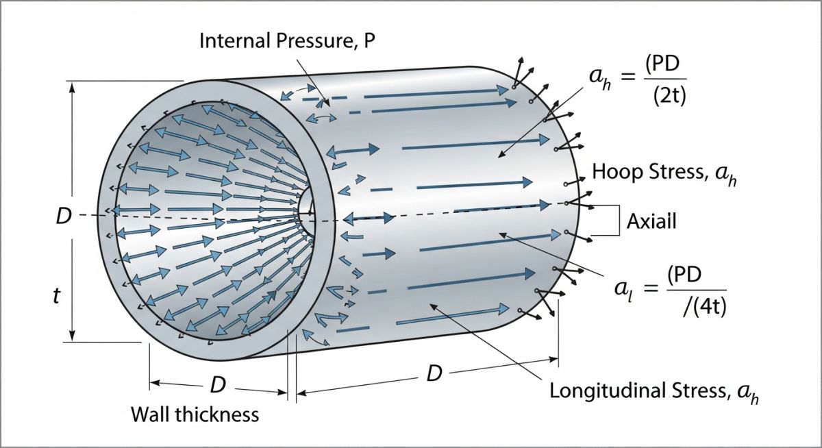
To truly comprehend the design formulas in ASME Section VIII Division 1, we must first look at the mechanics of thin-walled and thick-walled cylinders. When a vessel is subjected to internal pressure, it experiences three principal stresses: hoop (circumferential) stress, longitudinal (axial) stress, and radial stress.
For thin-walled cylinders (where the ratio of inner radius to wall thickness is greater than 10), we assume that the hoop stress is uniform across the wall thickness. The classical mechanics formula for hoop stress is:
Where:
• P = Internal design pressure (psi or MPa)
• D = Inside diameter of the cylinder (inches or mm)
• t = Wall thickness (inches or mm)
Similarly, the longitudinal stress is calculated as:
Notice that the hoop stress is exactly twice the longitudinal stress. This fundamental mechanical reality explains why longitudinal seams in welded pipes and vessels are subjected to double the stress of circumferential seams. Consequently, ASME codes require more stringent non-destructive examination (NDE) on longitudinal welds.
Thick-Walled Cylinders and Lame’s Equations
When the wall thickness exceeds 10 percent of the radius, the thin-walled assumption is no longer valid. The stress distribution across the wall becomes highly non-linear, with the maximum hoop stress occurring at the innermost fibers. In these scenarios, we must apply Lame’s equations, which form the basis of the thick-wall formulas found in ASME Section VIII Division 1, Appendix 1.
In our course, we walk through the derivation of these equations step-by-step. You will learn how to transition from pure mechanics to the code-specified formulas, ensuring you understand the safety factors and joint efficiency factors embedded within the code equations.
Standard Stress Limits and Equations
The table below outlines common materials used in pressure vessel and piping fabrication, along with their typical allowable stress limits at various design temperatures as specified in ASME Section II Part D.
| Material Grade | ASME Specification | Min. Yield Strength (ksi) | Min. Tensile Strength (ksi) | Max. Allowable Stress at 100°F (ksi) |
|---|---|---|---|---|
| SA-516 Gr. 70 | Carbon Steel Plate | 38.0 | 70.0 | 20.0 |
| SA-106 Gr. B | Seamless Carbon Pipe | 35.0 | 60.0 | 17.1 |
| SA-312 TP316 | Stainless Steel Pipe | 30.0 | 75.0 | 20.0 |
| SA-387 Gr. 11 | Low Alloy Steel Plate | 30.0 | 60.0 | 17.1 |
To help you navigate the relationship between engineering mechanics and code compliance, this matrix maps core physical parameters to their corresponding governing codes and formulas.
| Engineering Entity | Primary Code Reference | Governing Parameter | Physical Significance |
|---|---|---|---|
| Primary Membrane Stress | ASME Sec VIII Div 1 UG-27 | Internal Pressure | Prevents overall plastic deformation and burst. |
| Secondary Stress | ASME B31.3 Chapter II | Thermal Expansion | Self-limiting stress; prevents fatigue failure. |
| External Pressure Buckling | ASME Sec VIII Div 1 UG-28 | Geometric L/D and D/t ratios | Prevents structural collapse under vacuum. |
| Occasional Stress | ASME B31.3 Para 302.3.6 | Wind and Seismic Loads | Prevents structural failure during environmental events. |
Pressure Vessel Design Verification Checklist
Before signing off on any pressure vessel design, I always run through a rigorous verification process. Below is the exact checklist I use to ensure that the fundamental engineering mechanics have been correctly translated into code-compliant parameters.
Verification Checkpoints
-
Design Pressure and Temperature: Verify that the Maximum Allowable Working Pressure (MAWP) has been established with an adequate margin above the operating pressure, in accordance with ASME Section VIII Division 1 UG-21.
-
Corrosion Allowance Integration: Ensure that the specified corrosion allowance has been added to the calculated minimum wall thickness for all pressure-retaining parts, including shells, heads, and nozzles.
-
Joint Efficiency (E) Selection: Confirm that the joint efficiency factor matches the degree of radiographic examination (Full, Spot, or None) as defined in UW-12.
-
Nozzle Reinforcement Calculations: Check that the area replacement method (UG-37) has been satisfied for all openings, ensuring that the metal area removed is fully compensated by adjacent reinforcement.
-
Wind and Seismic Loading: Verify that external environmental loads have been combined with internal pressure loads using the correct load combinations from ASCE 7 or local building codes.
-
Hydrostatic Test Pressure: Ensure the hydrotest pressure is calculated correctly (minimum 1.3 times the MAWP multiplied by the temperature stress ratio) per UG-99.
Excel With ASME Piping and Pressure Vessel Codes Course
Field Case Study: Real-World Application
The Problem: Nozzle Cracking in a High-Temperature Steam Line
At a petrochemical plant in Texas, a 12-inch steam line operating at 450°C was experiencing repeated cracking at the nozzle connection of a critical pressure vessel. The original design team had attempted to solve the issue by increasing the nozzle wall thickness and adding heavy gussets.
However, this modification actually increased the local stiffness of the nozzle, which in turn increased the thermal expansion stresses transferred from the piping system. The nozzle cracked again within six months of operation.
The Outcome: Applying Flexibility Analysis and Mechanics
When my team was called in, we performed a comprehensive piping flexibility analysis in accordance with ASME B31.3 Chapter II. We realized that the piping layout lacked adequate flexibility to absorb the thermal expansion.
Instead of stiffening the nozzle, we introduced a 3D expansion loop in the piping run and replaced two rigid supports with spring hangers. This allowed the piping to expand naturally, reducing the bending moment on the vessel nozzle by 65 percent. The system has now been operating for over five years without a single sign of fatigue or cracking.
This case study highlights why a deep understanding of engineering mechanics is superior to blindly following code formulas. By understanding how thermal expansion translates into force and moment, you can design systems that are both safer and more cost-effective.
Frequently Asked Engineering Questions
What is the difference between ASME B31.1 and ASME B31.3?
How does engineering mechanics dictate the choice of joint efficiency?
Why does ASME Section VIII Division 1 use the Tresca criterion?
What is the significance of the MDMT in pressure vessel design?
How do thermal stresses differ from primary pressure stresses?
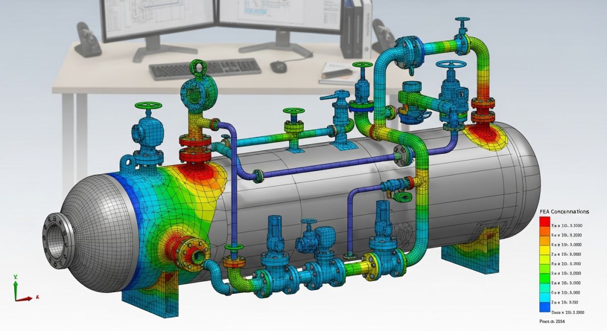
When must a full finite element analysis (FEA) be performed?
===


