Air Separation Unit Explained: Engineering Principles and Industrial Gas Production
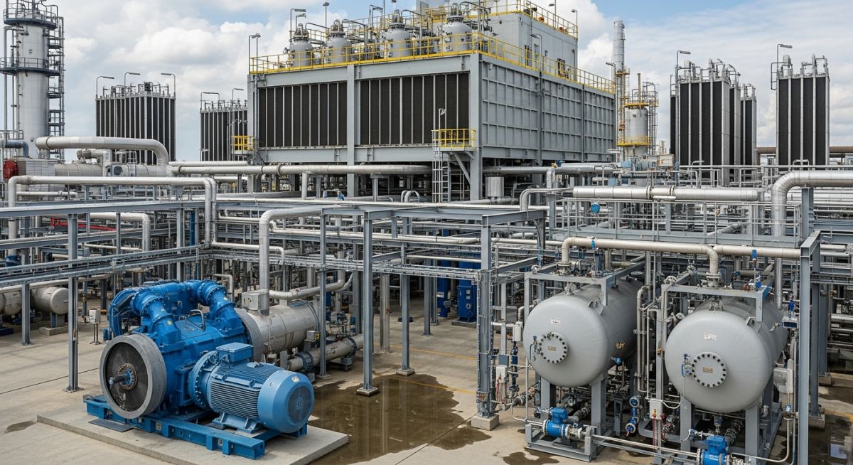
In my two decades of piping and process engineering, I have found that few systems demand as much precision as an Air Separation Unit (ASU). These plants are the lifeblood of modern heavy industry, converting ambient air into high-purity gases that drive everything from steel manufacturing to ammonia synthesis. The complexity lies not just in the cryogenic temperatures, but in the seamless integration of high-pressure compression, molecular sieve purification, and the delicate thermal balance of the cold box.
When we design these units, we are essentially managing a massive heat exchange challenge. Every stage—from the initial intake through the multi-stage centrifugal compressors to the final distillation columns—must be optimized for energy efficiency and structural integrity. This article breaks down the engineering architecture required to maintain stable, high-yield production in demanding industrial environments.
Key Engineering Takeaways
- Cryogenic distillation relies on the precise boiling point differences between nitrogen, oxygen, and argon.
- Multi-stage compression requires rigorous surge control and inter-stage cooling to prevent thermal degradation.
- Molecular sieve units are mandatory to remove moisture and carbon dioxide before the air enters the cold box.
- Integration with ammonia plants requires careful pressure balancing to optimize the air-to-fuel ratio.
Complete Course on
Piping Engineering
Check Now
Key Features
- 125+ Hours Content
- 500+ Recorded Lectures
- 20+ Years Exp.
- Lifetime Access
Coverage
- Codes & Standards
- Layouts & Design
- Material Eng.
- Stress Analysis
Engineering the Air Separation Unit Process
Air Separation Unit Process Engineering: The systematic conversion of atmospheric air into high-purity gaseous or liquid products using multi-stage compression, adsorption-based purification, and cryogenic rectification as defined by international process safety standards.
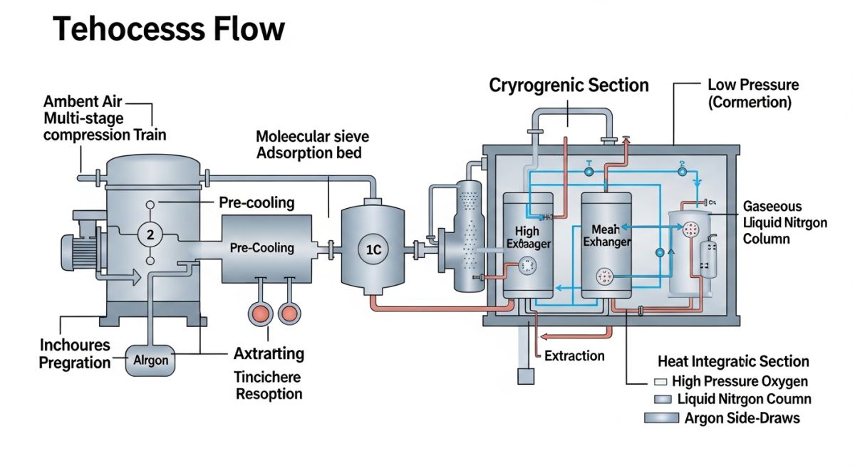
The core of any ASU is the cold box, a vacuum-insulated vessel containing the distillation columns and heat exchangers. Before air reaches this stage, it must undergo rigorous preparation. We start with atmospheric air, which is filtered and compressed. In my experience, the selection of the compressor train—typically multi-stage centrifugal units—is the most significant factor in plant energy consumption. These compressors must adhere to API 617 standards for axial and centrifugal compressors.
Compression and Purification Dynamics
After compression, the air is hot and contains contaminants. We utilize Pre-Purification Units (PPU) equipped with molecular sieves to remove water vapor, carbon dioxide, and hydrocarbons. If these are not removed, they will freeze in the cryogenic section, leading to catastrophic blockages and potential pressure surges. The PPU operates on a temperature swing adsorption (TSA) cycle, which requires careful piping design to handle the thermal cycling of the regeneration gas.
Field Warning: Cryogenic Embrittlement
Materials selection is non-negotiable. At temperatures below -150 degrees Celsius, standard carbon steels undergo a ductile-to-brittle transition. We exclusively use austenitic stainless steels (such as 304L or 316L) or aluminum alloys for all piping and vessels within the cold box to ensure structural integrity under cryogenic stress.
Cryogenic Distillation Calculations
The separation process relies on the relative volatility of oxygen and nitrogen. The air is cooled to near-liquefaction temperatures using a series of plate-fin heat exchangers. The expansion of the air through a turbo-expander provides the necessary refrigeration effect. The distillation column operates on the principle of counter-current contact between rising vapor and falling liquid. The reflux ratio must be strictly controlled to maintain product purity; for oxygen, this is often 99.5 percent or higher.
The energy balance for the column is governed by the mass flow rate of the feed air and the enthalpy change across the heat exchangers. We calculate the required refrigeration capacity based on the heat leak into the cold box and the enthalpy of the product streams. Any deviation in the feed air composition or pressure will immediately impact the purity of the nitrogen and oxygen streams, requiring a robust Distributed Control System (DCS) to manage the valve positions in real-time.
ASU Operational Performance: The comparative analysis of cryogenic air separation technology regarding energy efficiency, product purity, and capital expenditure requirements for large-scale industrial gas facilities.
Advantages
- High-purity output suitable for medical and electronic grade applications.
- Scalability for massive industrial throughput requirements.
- Ability to produce liquid products for storage and transport.
- Long operational lifespan with established maintenance protocols.
- High reliability for continuous, 24/7 base-load operations.
Disadvantages
- Extremely high initial capital expenditure for cryogenic infrastructure.
- Significant energy consumption during the compression phase.
- Long startup times to reach cryogenic equilibrium.
- Complex safety requirements for handling liquid oxygen.
- Sensitivity to ambient air temperature and humidity fluctuations.
Industrial Gas Utilization: The strategic deployment of ASU-derived oxygen and nitrogen across heavy manufacturing, chemical synthesis, and energy sectors to optimize process efficiency and product quality.
Ammonia Plant Integration
ASUs provide high-purity nitrogen for the Haber-Bosch process, which is the foundation of global fertilizer production. By integrating the ASU with the ammonia plant, we can optimize the air-to-fuel ratio in the secondary reformer, significantly reducing energy waste and improving overall plant yield.
Steel Manufacturing and Oxygen Enrichment
In basic oxygen furnaces, high-purity oxygen is injected to accelerate the oxidation of carbon and impurities in molten iron. This process drastically reduces the time required for steel production while simultaneously increasing the furnace temperature, allowing for higher scrap metal recycling rates.
Coal Gasification and Syngas Production
Large-scale gasification plants rely on ASU-supplied oxygen to convert coal or biomass into syngas. This syngas serves as a versatile feedstock for chemical synthesis or power generation, where the oxygen purity directly influences the efficiency of the gasifier and the downstream cleanup systems.
In my two decades of experience with cryogenic systems, I have found that the efficiency of an Air Separation Unit (ASU) is dictated by the precise control of thermodynamic variables across the compression and distillation stages. The following table outlines the critical design parameters that engineers must monitor to ensure compliance with ASME pressure vessel codes and API standards for rotating equipment.
These values represent typical operating ranges for large-scale industrial plants. Deviations from these setpoints often indicate fouling in the molecular sieve beds or efficiency losses in the main air compressor (MAC) intercoolers, which directly impacts the specific power consumption per unit of oxygen produced.
| Parameter | Typical Range | Standard Reference |
|---|---|---|
| MAC Discharge Pressure | 5.5 to 6.5 bar(a) | API 617 |
| Purification Bed Temp | 10 to 35 degrees C | ASME B31.3 |
| Distillation Column Pressure | 1.2 to 5.0 bar(a) | ASME BPVC VIII |
| Oxygen Purity | 95 to 99.8 percent | ISO 8573 |
Engineers should note that maintaining these parameters requires a robust Distributed Control System (DCS) capable of handling high-speed transient responses during load changes. Always verify that your instrumentation calibration cycles align with the manufacturer’s recommendations to prevent drift in critical flow measurements.
The complexity of an Air Separation Unit requires a clear understanding of the interplay between mechanical components and process fluids. This matrix maps the primary equipment entities to their respective physical functions and the governing engineering standards that dictate their design and safety requirements.
By standardizing these definitions, we ensure that maintenance teams and process engineers share a common language when troubleshooting performance bottlenecks or planning turnarounds. Referencing these standards during the procurement phase is vital for ensuring long-term equipment reliability and safety.
| Equipment | Function | Standard |
|---|---|---|
| Main Air Compressor | Atmospheric air intake and pressurization | API 672 |
| Molecular Sieve Unit | Removal of H2O, CO2, and hydrocarbons | ASME VIII |
| Cryogenic Heat Exchanger | Multi-stream heat transfer for cooling | TEMA |
| Distillation Column | Separation of N2, O2, and Argon | ASME BPVC |
This matrix serves as a foundational reference for site-specific risk assessments. When integrating new equipment, always cross-reference these standards with local jurisdictional requirements to ensure full compliance with regional safety mandates.
Commissioning an Air Separation Unit is a high-stakes operation that demands rigorous attention to detail. Before introducing process air into the system, I always mandate a comprehensive verification of the mechanical, electrical, and control systems to prevent catastrophic failure or contamination of the cryogenic cold box.
-
Piping Integrity: Verify all flange torque values against ASME PCC-1 guidelines to ensure leak-free operation at cryogenic temperatures. -
Purification Bed Loading: Confirm the molecular sieve material is correctly graded and packed to prevent channeling, as per manufacturer specifications. -
Instrumentation Loop Checks: Validate all pressure, temperature, and flow transmitters against ISA-5.1 standards to ensure accurate DCS feedback. -
Safety Relief Systems: Inspect all cryogenic relief valves for proper set-pressure verification and ensure discharge piping is clear of obstructions. -
Cold Box Insulation: Perform a vacuum leak test on the cold box casing to ensure the integrity of the perlite or vacuum insulation system.
Following these steps is not merely a procedural requirement; it is a safeguard against the significant financial and safety risks associated with ASU downtime. Always document every check with signed-off inspection reports to maintain a clear audit trail for regulatory bodies and insurance underwriters.
Field Case Study: Real-World Application
Problem: Unexpected Pressure Drop in Molecular Sieve Unit
A mid-sized ASU experienced a sudden, unexplained increase in pressure drop across the purification beds, leading to a 15 percent reduction in total air throughput.
- Contamination of the adsorbent bed due to upstream compressor oil carryover.
- Inadequate regeneration cycle times failing to remove accumulated moisture.
- Physical degradation of the molecular sieve beads caused by excessive flow velocity.
- Failure of the inlet air filtration system allowing particulate ingress.
Outcome: Restored Efficiency and Optimized Cycle Times
By implementing a comprehensive remediation strategy, the plant successfully restored full operational capacity within 72 hours of the intervention.
- Replacement of the contaminated adsorbent material with high-performance molecular sieve beads.
- Installation of an upgraded oil-mist separator at the compressor discharge.
- Optimization of the regeneration temperature profile to ensure complete moisture desorption.
- Implementation of a predictive maintenance schedule based on real-time pressure drop monitoring.
My recommendation for similar facilities is to prioritize the health of the purification system. Investing in high-quality filtration and rigorous monitoring of the regeneration cycle is the most effective way to prevent costly, unplanned outages in your cryogenic process.
Frequently Asked Engineering Questions
How does the cryogenic distillation process achieve high purity?
- The high-pressure column performs the initial separation into nitrogen-rich and oxygen-rich streams.
- The low-pressure column refines these streams to achieve the desired product purity levels.
- Reflux ratios are strictly controlled to ensure that impurities are effectively stripped from the product streams.
- Adherence to ASME BPVC standards is mandatory for the design of these columns to handle the extreme thermal stresses.
What is the role of the molecular sieve in an ASU?
- It utilizes adsorption beds that operate on a cyclic basis, with one bed in service while the other is being regenerated.
- Regeneration is typically achieved using waste nitrogen heated to specific temperatures to drive off the adsorbed impurities.
- Proper management of the regeneration cycle is critical to prevent the breakthrough of contaminants into the cold box.
- Failure to maintain this system can lead to severe icing, which poses a significant safety risk to the entire plant.
Why is energy consumption so high in ASU operations?
- The main air compressor accounts for the majority of the plant’s total power demand.
- Efficiency losses in intercoolers and the expansion turbine directly increase the specific energy consumption.
- Modern plants utilize advanced control strategies to optimize compressor performance based on real-time demand.
- Integration with other processes, such as ammonia production, can help recover some of this energy through heat integration.
How are ASU units integrated with ammonia plants?
- The ASU supplies high-purity nitrogen to the ammonia synthesis loop.
- Oxygen produced as a byproduct can be utilized in other plant processes, such as partial oxidation or waste treatment.
- Heat integration between the two units can significantly improve the overall thermal efficiency of the facility.
- Coordinated control systems ensure that the ASU output matches the fluctuating demands of the ammonia plant.
What are the safety risks associated with oxygen production?
- Hydrocarbon accumulation can lead to explosive conditions if not properly managed.
- Strict adherence to CGA standards for oxygen service is essential for all piping and equipment.
- Regular analysis of the liquid oxygen stream is required to monitor hydrocarbon concentrations.
- Personnel must be trained in the specific hazards of oxygen-enriched environments and the use of oxygen-compatible lubricants.
How do I select the right ASU for my facility?
- Evaluate the trade-off between capital expenditure and operational efficiency.
- Consider the reliability of the technology provider and their track record in similar industrial applications.
- Ensure that the design complies with all relevant international standards and local safety regulations.
- Engage with experienced process engineers to conduct a thorough feasibility study before finalizing your procurement strategy.
