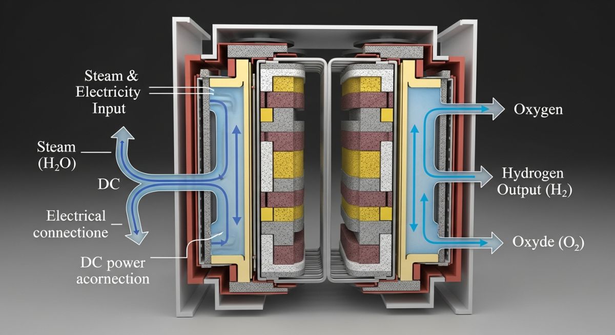
SOEC Electrolyzer Explained: High Temperature Electrolysis for Green Hydrogen Production
In my two decades of piping and process engineering, I have seen many technologies promise a revolution in green hydrogen, but Solid Oxide Electrolysis Cells (SOEC) stand apart due to their unique thermal integration capabilities. Unlike PEM or Alkaline systems, SOEC operates at temperatures between 600 and 850 degrees Celsius, which allows the system to leverage waste heat from industrial processes to reduce the electrical energy required for water splitting.
This shift from purely electrical input to a thermo-electrical balance is a game-changer for heavy industry. When we design these systems, we are not just looking at power density; we are looking at heat recovery loops, high-temperature material compatibility, and the complex piping stress analysis required for steam-fed electrolyzer stacks.
Key Takeaways for Engineers:
- SOEC systems achieve electrical efficiencies exceeding 90 percent LHV.
- High-temperature operation enables co-electrolysis of steam and carbon dioxide.
- Thermal management is the primary driver of system longevity and performance.
- Material selection must account for extreme thermal cycling and steam corrosion.
Complete Course on
Piping Engineering
Check Now
Key Features
- 125+ Hours Content
- 500+ Recorded Lectures
- 20+ Years Exp.
- Lifetime Access
Coverage
- Codes & Standards
- Layouts & Design
- Material Eng.
- Stress Analysis
Technical Deep-Dive: SOEC Electrolyzer Design and Thermodynamic Principles
SOEC Electrolyzer Design: The core of SOEC technology relies on a solid ceramic electrolyte, typically Yttria-Stabilized Zirconia (YSZ), which conducts oxygen ions at elevated temperatures while maintaining structural integrity under high-pressure steam conditions.
From a process engineering perspective, the SOEC stack functions as a reversible fuel cell. By applying a DC current, we drive the oxygen ions from the steam side (cathode) through the electrolyte to the anode, where they recombine to form oxygen gas. The fundamental advantage here is the reduction in Gibbs free energy required for the reaction as temperature increases.
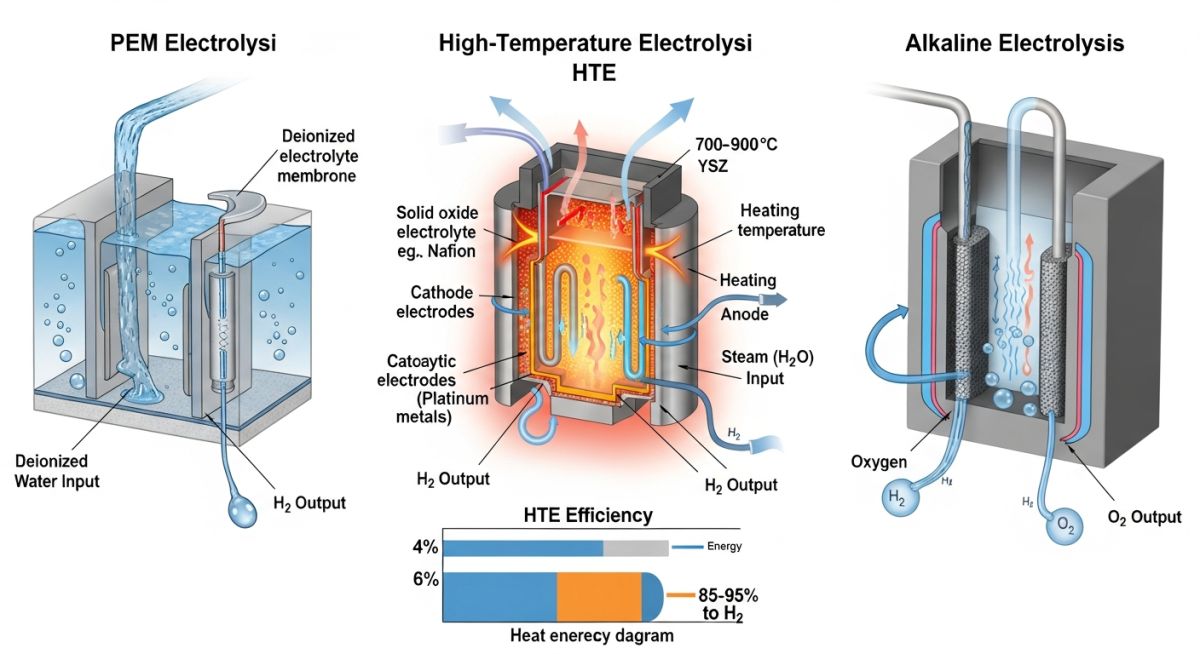
Thermodynamic Efficiency Calculations
The electrical energy demand for water electrolysis is defined by the change in Gibbs free energy. As we increase the operating temperature, the electrical energy requirement decreases, while the thermal energy requirement increases. The total energy required remains constant, but the cost of electricity is significantly lower than the cost of high-grade heat.
In my experience, the efficiency calculation follows the ratio of the lower heating value of hydrogen to the total energy input. For an SOEC system, the efficiency is expressed as:
When designing the piping headers for these stacks, we must adhere to ASME B31.3 for process piping, specifically addressing the thermal expansion of high-temperature steam lines. The differential thermal expansion between the ceramic stack and the metallic manifold requires flexible piping configurations or bellows to prevent mechanical stress on the brittle ceramic components.
Field Warning: Thermal Cycling Risks
The most common failure mode in SOEC systems is the degradation of the ceramic-to-metal seal due to rapid thermal cycling. Engineers must implement strict ramp-up and ramp-down protocols to ensure the temperature gradient across the stack remains within the manufacturer’s specified limits, typically below 2 degrees Celsius per minute.
Furthermore, the integration of ISO 22734 standards for hydrogen generators is critical. We must ensure that the balance of plant (BoP) components, including heat exchangers and steam generators, are rated for the specific steam quality required by the SOEC stack to prevent poisoning of the nickel-cermet electrodes.
SOEC Electrolyzer Performance: The operational profile of SOEC systems presents a unique trade-off between high thermodynamic efficiency and the challenges associated with high-temperature material degradation and system complexity.
Advantages
- Superior electrical efficiency compared to PEM or Alkaline.
- Ability to utilize industrial waste heat for steam generation.
- Co-electrolysis capability for syngas production (H2 + CO).
- Reduced noble metal catalyst requirements.
- High power density per unit volume.
Disadvantages
- High susceptibility to thermal shock and mechanical stress.
- Complex material requirements for high-temperature seals.
- Longer startup and shutdown times due to thermal inertia.
- Degradation of ceramic electrolyte over extended cycles.
- Higher initial CAPEX for specialized high-temperature alloys.
SOEC Electrolyzer Integration: The versatility of high-temperature electrolysis allows for seamless integration into existing industrial clusters where waste heat and steam are readily available as byproducts.
Industrial Feedstock Decarbonization
SOEC systems are ideal for ammonia and methanol production facilities where high-pressure steam is a standard utility. By integrating the electrolyzer into the existing steam loop, plants can replace fossil-fuel-derived hydrogen with green hydrogen while simultaneously recovering heat from the exothermic synthesis reactors.
Syngas and Synthetic Fuel Production
Through the co-electrolysis of steam and carbon dioxide, SOEC units produce syngas directly, which serves as a precursor for Fischer-Tropsch synthetic fuels. This process bypasses the need for separate water-gas shift reactors, significantly simplifying the process flow and reducing the overall plant footprint.
Steel Industry Heat Recovery
Steel manufacturing generates massive quantities of high-grade waste heat from blast furnaces and direct reduction processes. SOEC electrolyzers can capture this thermal energy to drive the electrolysis reaction, effectively turning a waste stream into a valuable hydrogen supply for green steel production.
The performance of a Solid Oxide Electrolyzer Cell (SOEC) is fundamentally dictated by the thermodynamic interplay between high-temperature steam and the ceramic electrolyte structure. Unlike PEM or Alkaline systems, SOEC operates in the range of 600 to 850 degrees Celsius, which significantly reduces the electrical energy required for water splitting by substituting it with thermal energy. This shift in the energy balance requires rigorous material selection to prevent degradation of the nickel-cermet fuel electrode and the perovskite-based oxygen electrode.
The following table outlines the critical operating thresholds and material compatibility requirements for industrial-scale SOEC stacks. Engineers must ensure that the piping and balance-of-plant components are rated for these specific thermal cycles to avoid creep-fatigue failure and hydrogen embrittlement in downstream metallic piping systems. Adherence to ASME B31.3 for high-temperature process piping is mandatory when designing the steam supply and hydrogen collection manifolds.
| Parameter | Operating Range | Material/Standard |
|---|---|---|
| Operating Temperature | 600 – 850 Celsius | Inconel 625 / Hastelloy |
| Steam Pressure | 1 – 20 Bar | ASME Section VIII |
| Current Density | 0.5 – 1.5 A/cm2 | Ceramic Electrolyte (YSZ) |
| Hydrogen Purity | 99.9% + | ISO 14687 |
To effectively integrate SOEC technology into existing industrial clusters, engineers must map the relationship between electrochemical entities and their corresponding physical infrastructure. This matrix serves as a technical bridge between the microscopic reaction kinetics occurring within the ceramic cells and the macroscopic piping and instrumentation requirements found in a typical hydrogen production facility.
Each entity listed below represents a critical node in the process flow, requiring specific attention during the Front-End Engineering Design (FEED) phase. By aligning these parameters with established international standards, we ensure that the system remains compliant with safety protocols while maximizing the thermodynamic efficiency of the high-temperature electrolysis process.
| Entity | Function | Standard Reference |
|---|---|---|
| YSZ Electrolyte | Ion Transport | ASTM C1161 |
| Interconnects | Electrical Series Connection | ASME B16.5 |
| Steam Generator | Phase Change/Heating | ASME BPVC I |
| Hydrogen Purification | Gas Separation/Drying | ISO 19880 |
Implementing an SOEC electrolyzer requires a rigorous site verification process to ensure that the high-temperature environment is safely contained and that the thermal integration with the host facility is optimized. In my experience, the most common failures occur not in the cell stack itself, but in the peripheral piping and heat exchange interfaces where thermal expansion and material compatibility are overlooked.
-
01.
Verify thermal expansion loops in steam supply lines to accommodate 850 Celsius operation per ASME B31.3. -
02.
Confirm electrical isolation of the stack from the metallic support structure to prevent stray current corrosion. -
03.
Validate the purity of the feed water to prevent poisoning of the nickel-cermet electrodes, adhering to ASTM D1193. -
04.
Inspect hydrogen collection manifolds for potential hydrogen embrittlement risks in high-pressure zones. -
05.
Ensure redundant temperature sensors are installed at the stack inlet and outlet for real-time thermal gradient monitoring.
Before commissioning, perform a full pressure test using inert gas to verify the integrity of all ceramic-to-metal seals. Any leakage at these interfaces can lead to catastrophic oxidation of the interconnects. Always document the thermal ramp-up rate, as rapid heating can induce micro-cracking in the electrolyte layers, significantly reducing the operational lifespan of the SOEC module.
Field Case Study: Real-World Application
Problem: Thermal Stress Induced Seal Failure
A pilot-scale SOEC installation experienced premature gas leakage at the stack manifold interface during the initial heat-up cycle.
- Inadequate allowance for differential thermal expansion between the ceramic stack and the stainless steel housing.
- Rapid ramp-up rates exceeding the manufacturer’s recommended 2 degrees Celsius per minute.
- Improper torque application on the manifold bolts during cold assembly.
Outcome: Optimized Thermal Management and Seal Integrity
Following the implementation of a revised thermal management protocol, the system achieved stable operation with zero leakage.
- Installation of spring-loaded bolt tensioners to maintain constant pressure during thermal cycling.
- Implementation of a PLC-controlled ramp-up sequence with a 0.5 degree Celsius per minute limit.
- Replacement of standard gaskets with high-temperature mica-based seals compatible with the operating environment.
Recommendation: Always prioritize thermal expansion analysis in the piping design phase for high-temperature electrolysis systems. Use flexible connections and ensure that the structural support allows for free movement of the stack assembly during all operational states.
Frequently Asked Engineering Questions
How does SOEC efficiency compare to PEM electrolysis?
- The high-temperature environment reduces the Gibbs free energy required for electrolysis.
- System efficiency can exceed 90 percent when integrated with waste heat sources from industrial processes.
- PEM systems are limited by the lower operating temperature, requiring more electrical input to achieve the same hydrogen output.
What are the primary degradation mechanisms in SOEC?
- Nickel migration and agglomeration in the fuel electrode reduce the active surface area over time.
- Chromium poisoning from the metallic interconnects can severely degrade the oxygen electrode performance.
- Thermal cycling induces mechanical stress, leading to delamination of the electrolyte-electrode interfaces.
Can SOEC operate in reversible mode?
- This dual-mode capability allows for energy storage during peak renewable generation and power production during high demand.
- The reversible operation requires sophisticated control systems to manage the transition between electrolysis and fuel cell modes.
- Material durability is the main challenge for long-term reversible operation due to the frequent thermal and chemical cycling.
What materials are used for SOEC interconnects?
- Ferritic stainless steels are commonly used due to their thermal expansion coefficient matching the ceramic components.
- Protective coatings, such as manganese-cobalt spinels, are applied to prevent chromium evaporation and poisoning.
- The design must ensure low contact resistance to maintain high stack efficiency throughout the operational life.
How is steam quality managed in SOEC?
- Feed water must be deionized and deoxygenated to meet strict purity standards.
- Steam generators must be designed to provide a stable, superheated steam flow to the stack inlet.
- Real-time monitoring of steam purity and flow rate is essential for maintaining the long-term health of the SOEC stack.
What are the safety considerations for SOEC?
- Leak detection systems must be installed in all hydrogen-containing areas to prevent explosive atmospheres.
- Thermal insulation is required to protect personnel and prevent heat loss from the high-temperature components.
- Emergency shutdown procedures must be automated to safely isolate the stack in the event of a process deviation.
