Table of Contents
Actuators in Piping Systems: Definition, Types, and Selection Guide
During my 20 years in the piping engineering field, I have seen many projects suffer from poorly specified valve automation. I remember a petrochemical expansion project where a major line shutdown occurred because someone overlooked the breakout torque of a high-pressure ball valve. The actuator stalled halfway through its stroke. This taught me that understanding actuators is not just about choosing between pneumatic or electric power. It requires a deep understanding of mechanical force, fluid dynamics, and control system integration.
In this guide, I will share my practical experience to help you understand industrial actuators. We will look at their internal components, calculate their output forces, compare different power sources, and establish a reliable selection process. Whether you are designing a new process plant or troubleshooting an existing system, this guide will provide the technical details you need to make informed decisions.
What You Will Learn in This Guide
- The mechanical components that make up modern industrial actuators.
- How to calculate pneumatic actuator thrust using design formulas.
- A detailed comparison of pneumatic, hydraulic, and electric actuators.
- A step-by-step selection process to prevent actuator sizing errors in the field.
Complete Course on
Piping Engineering
Check Now
Key Features
- 125+ Hours Content
- 500+ Recorded Lectures
- 20+ Years Exp.
- Lifetime Access
Coverage
- Codes & Standards
- Layouts & Design
- Material Eng.
- Stress Analysis
To select the right actuator, you must first understand how it works. At its core, an actuator takes energy—whether compressed air, hydraulic fluid, or electricity—and converts it into linear or rotary motion. This motion is transferred directly to the valve stem to open, close, or modulate the valve.
Key Components of an Actuator
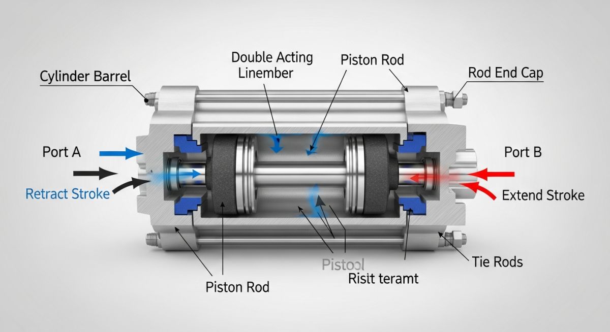
A standard industrial actuator consists of several critical parts working together:
- Power Source/Drive Mechanism: The piston, diaphragm, or electric motor that generates the initial force.
- Stem/Shaft Connection: The mechanical link that transmits force from the actuator to the valve stem.
- Spring Return Assembly: A safety feature in spring-return actuators that uses a mechanical spring to return the valve to a safe position (fail-open or fail-closed) if power is lost.
- Yoke: The structural support that mounts the actuator to the valve body and protects the stem connection.
- Positioner/Controller: An instrument that monitors stem position and adjusts the power input to match the control signal.
Pneumatic Actuator Thrust Calculation
Let’s look at how to calculate the output force of a pneumatic diaphragm actuator. This is a common task when sizing control valves. The net thrust must overcome both the valve packing friction and the dynamic process forces acting on the valve plug.
The formula for the net output thrust of a spring-return pneumatic diaphragm actuator during the air stroke is:
Where:
- F_net: Net output thrust available to move the valve stem (Newtons, N).
- A: Effective area of the actuator diaphragm (square meters, m²).
- P: Supply air pressure applied to the diaphragm (Pascals, Pa).
- F_spring: Opposing force exerted by the compressed spring at the end of the stroke (Newtons, N).
Sample Calculation:
Consider a control valve with the following parameters:
- Effective Diaphragm Area (A) = 0.08 m² (approx. 124 in²)
- Supply Air Pressure (P) = 300,000 Pa (3.0 bar or approx. 43.5 psi)
- Spring Force at full compression (F_spring) = 14,000 N
First, calculate the gross force generated by the air pressure on the diaphragm:
Next, subtract the spring force to find the net thrust available to close the valve:
This net thrust of 10,000 N must be compared against the valve manufacturer’s required seating force. I always recommend adding a safety margin of at least 20% to 30% to account for packing degradation over time.
In my years in the field, I have seen many engineers size actuators based only on the running torque of a clean valve. Over time, process fluids can cause scale buildup, and packing can dry out. This significantly increases the torque needed to open a valve that has been closed for a long time. This is known as “breakout torque.” Always size your actuator to handle this maximum breakout torque, not just the normal running torque.
The table below compares the three primary types of industrial actuators. This comparison is based on my experience with plant designs and standard industry guidelines, including ISA Standards.
| Parameter | Pneumatic Actuators | Hydraulic Actuators | Electric Actuators |
|---|---|---|---|
| Power Source | Compressed Air (3 to 10 bar) | High-Pressure Oil (up to 210 bar) | AC/DC Electricity |
| Thrust/Torque Output | Moderate to High | Extremely High | Moderate to High |
| Operating Speed | Fast (0.5 to 5 seconds) | Fast and highly adjustable | Slow (typically 10 to 60 seconds) |
| Fail-Safe Capability | Excellent (via mechanical springs) | Excellent (via accumulators) | Limited (requires batteries/springs) |
| Hazardous Area Use | Inherently Safe | Safe (with proper fluid choice) | Requires explosion-proof housing |
| Maintenance Needs | Low (seal replacements) | High (fluid leaks, filtration) | Low to Moderate (gear lubrication) |
This matrix maps key technical terms, acronyms, and physical parameters to their governing industry standards. This helps ensure your designs comply with international engineering practices.
| Technical Entity | Acronym | Primary Physical Parameter | Governing Standard Reference |
|---|---|---|---|
| Maximum Allowable Stem Torque | MAST | Newton-meters (Nm) / Foot-pounds | API Standard 6D |
| Safety Integrity Level | SIL | Probability of Failure on Demand (PFD) | IEC 61508 / IEC 61511 |
| Ingress Protection | IP Rating | Dust and Water Resistance Levels | IEC 60529 |
| Valve Mounting Interface | ISO Flange | Bolt Circle Diameter & Keyway Dimensions | ISO 5211 / ISO 5210 |
Before commissioning any automated valve, the field engineering team must perform a thorough physical inspection. This checklist is based on my experience conducting pre-commissioning walks on large-scale industrial projects.
Pre-Commissioning Field Checklist
-
Mechanical Alignment: Verify that the actuator shaft is perfectly aligned with the valve stem. Misalignment causes side-loading, which damages the packing and seals.
-
Bolting Torque: Confirm that all mounting bolts on the ISO 5211 flange are tightened to the specified torque values using a calibrated torque wrench.
-
Air Supply Quality: Check that the pneumatic supply line has a clean, dry air source. The air must pass through a filter-regulator set to the correct operating pressure.
-
Fail-Safe Action: Test the fail-safe mode by cutting off power or air supply. Verify that the valve moves to its designated safe position (fail-open, fail-closed, or lock-in-last-position).
-
Limit Switch Calibration: Confirm that the limit switches accurately report the fully open and fully closed positions to the control room.
-
Earthing/Grounding: For electric actuators, ensure the housing is properly grounded to prevent electrical hazards and signal interference.
Field Case Study: Real-World Application
The Problem: Sticking Control Valve in a Gas Plant
At a natural gas processing facility, a critical 12-inch modulating control valve was failing to maintain the correct flow rate. The valve would stick in place and then suddenly jump, causing pressure spikes downstream. The plant operators suspected a faulty control signal. However, our investigation revealed that the pneumatic diaphragm actuator was undersized. It could not overcome the high dynamic packing friction and process differential pressure, which had increased due to trace contaminants in the gas stream.
The Solution and Outcome
We recalculated the required stem force using the maximum process differential pressure and the actual packing friction coefficient. We replaced the existing actuator with a larger, double-acting piston actuator equipped with a high-performance digital positioner. We also installed a volume tank to provide a stable air supply. After these changes, the valve operated smoothly, eliminating the downstream pressure spikes and improving process stability.
My recommendation from this experience is clear: never rely solely on standard catalog sizing tables for critical or high-pressure applications. Always perform a detailed force balance calculation that accounts for the worst-case process conditions and potential packing degradation.
Frequently Asked Engineering Questions
What is the difference between double-acting and spring-return actuators?
How do you calculate the safety factor for actuator sizing?
Why do electric actuators require duty cycle considerations?
What role does a positioner play in actuator operation?
How does ambient temperature affect pneumatic actuator seals?
Which standards govern the mounting interface of actuators?
===

📚 Recommended Resources: Actuators
Read these Guides
🎓 Advanced Training


Related posts:
![Mastering ASME BPVC Creep Design for High Temperature Vessels]()
Mastering ASME BPVC Creep Design for High Temperature Vessels
![What is Corrosion Under Insulation and How to Prevent It]()
What is Corrosion Under Insulation and How to Prevent It
![What is ASME B31.3 Pressure Leak Test Requirements]()
What is ASME B31.3 Pressure Leak Test Requirements
![What is the Minimum Distance Between Welds in Piping?]()
What is the Minimum Distance Between Welds in Piping?
![How Buried Pipeline Stress Analysis Coating Factor Impacts Piping Integrity]()
How Buried Pipeline Stress Analysis Coating Factor Impacts Piping Integrity
![Understanding the GRE Design Envelope for Safe Piping Operations]()
Understanding the GRE Design Envelope for Safe Piping Operations