Table of Contents
Emergency Shutdown System Design Working Components and Safety Logic
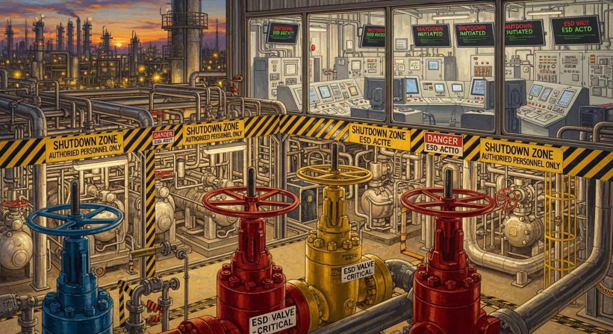
In my experience across large industrial projects—whether it’s a methanol plant or heavy steel facilities like JSPL—the Emergency Shutdown System is not just another control layer. It is the final defensive barrier between process instability and catastrophic failure.
I have seen plants lose crores due to poorly configured ESD logic and, at the same time, I’ve seen correctly engineered systems prevent major disaster during high-pressure excursions. The difference always lies in design philosophy, SIL validation, and real-world understanding—not just documentation.
This guide is built from real EPC execution challenges—covering working principles, system components, field mistakes, and engineering verification practices you cannot ignore at site.
- Emergency Shutdown System acts independently from basic process control systems
- Improper ESD logic design is a major cause of false trips and plant downtime
- Final control elements like ESD valves define real safety performance
- SIL rating selection must align with actual process hazards
- Cause & Effect matrix validation is the most critical commissioning step
Interactive Engineering Quiz
Q1: What is the primary purpose of an Emergency Shutdown System?
Complete Course on
Piping Engineering
Check Now
Key Features
- 125+ Hours Content
- 500+ Recorded Lectures
- 20+ Years Exp.
- Lifetime Access
Coverage
- Codes & Standards
- Layouts & Design
- Material Eng.
- Stress Analysis
What are core ESD system functions
Emergency Shutdown System Functions: An Emergency Shutdown System continuously monitors process parameters and triggers safe isolation when predefined limits are exceeded. It is designed as an independent safety layer complying with IEC 61511 and ensures hazard mitigation beyond basic control systems.
In real plant execution, I treat ESD as the last active protection before mechanical safeguards like relief valves take over. Its functions are not limited to shutdown — it defines controlled shutdown paths.
- Isolation of hydrocarbon or hazardous chemical inventory
- Depressurization through blowdown systems
- Shutdown of rotating equipment (compressors, pumps)
- Segregation of plant units based on escalation level
- Integration with fire & gas detection signals
How emergency shutdown system actually works
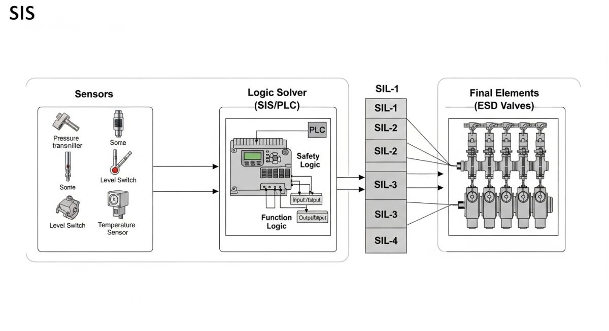
Emergency Shutdown System Working: The ESD system operates using a three-layer architecture—field sensors detect abnormal conditions, a logic solver processes these signals based on cause and effect matrices, and final elements execute shutdown actions.
From my site experience, failure rarely happens in sensing—it happens in logic interpretation or final actuation. That is where engineering focus must stay.
Stepwise logic execution sequence
- Sensor detects abnormality (Pressure > Setpoint)
- Signal transmitted to logic solver (SIS PLC)
- Voting logic applied (e.g., 2oo3 configuration)
- Trip decision generated
- Final element activation (ESD valve closure time typically 1–5 sec)
Engineering calculation: shutdown response time
Total ESD Response Time must satisfy process safety limits:
Total Response Time (TRT) = Sensor Delay + Logic Solver Scan Time + Final Element Stroke Time

Example:
Sensor Delay = 0.5 sec
Logic Solver = 0.2 sec
Valve Stroke Time = 2.5 sec

TRT = 0.5 + 0.2 + 2.5 = 3.2 seconds
Now compare TRT against process safety time (PST). If TRT exceeds PST, system fails SIL requirement.
Key emergency shutdown design considerations
Emergency Shutdown System Design Considerations: ESD design must ensure fail-safe operation, redundancy, SIL compliance, and independent architecture. Design philosophy should be derived from hazard and operability studies (HAZOP) and risk assessment.
I always insist that ESD design must originate from process risk — not from vendor templates.
Key design parameters to validate
- SIL Level determination (SIL 1 to SIL 3)
- Redundancy structure (1oo2, 2oo3 voting)
- Fail-safe position (Fail Close / Fail Open)
- Independence from DCS system
- Power supply reliability (UPS + Battery backup)
- Environmental conditions (temperature, dust, vibration)
| Parameter | Typical Value | Engineering Note |
|---|---|---|
| SIL Level | SIL 1 to SIL 3 | Determined via HAZOP and LOPA |
| Valve Stroke Time | 1–5 seconds | Critical for fast shutdown scenarios |
| Logic Solver Scan Time | 50–300 ms | Depends on PLC architecture |
| Voting Logic | 1oo2 / 2oo3 | Improves reliability and avoids false trips |
| Availability | > 99.9% | Achieved via redundancy and diagnostics |
| Entity | Function | Failure Impact | Standard Reference |
|---|---|---|---|
| Sensor (PT, TT, LT) | Detect abnormal condition | Delayed or missed trip | IEC 61511 |
| Logic Solver (SIS PLC) | Decision making unit | Wrong trip logic | IEC 61508 |
| Final Element (ESDV) | Execute shutdown | No physical isolation | API 6D, IEC 61511 |
| Fire & Gas System | Trigger ESD during hazards | Delayed emergency response | NFPA Codes |
Emergency Shutdown System Checklist: A structured checklist ensures the ESD system meets design intent, SIL requirements, and real field operability as per IEC 61511 lifecycle validation. It verifies independence, response time, and physical execution before energization.
In my projects—especially during commissioning at large chemical and steel plants—I insist on physical validation of ESD loops. Drawing reviews alone never capture wiring faults, actuator misalignment, or logic bypasses.
✅ Pre-Commissioning ESD Checklist
- Verify all ESD loops against approved Cause & Effect matrix
- Check sensor calibration certificates (PT, TT, LT)
- Confirm logic solver configuration matches SIL design
- Ensure ESD system is independent from DCS network
- Power supply redundancy (UPS + Battery backup) tested
✅ Functional Testing Requirements
- Loop checking from field sensor to logic solver to final element
- Simulate process trip conditions and observe system response
- Validate voting logic (1oo2, 2oo3) execution under fault scenarios
- Measure actual shutdown response time vs calculated TRT
- Confirm alarm and event logging accuracy
✅ Final Element Validation
- Check valve fail position (Fail Close / Fail Open)
- Measure valve stroke time with actual air pressure
- Inspect actuator spring return mechanism
- Verify solenoid valve operation and redundancy
- Ensure no mechanical obstruction in valve movement
✅ Safety and Documentation Checks
- HAZOP and LOPA recommendations implemented
- All bypasses removed and documented
- Shutdown hierarchy (ESD-1, ESD-2, ESD-3) confirmed
- Emergency shutdown push buttons tested at field and control room
- All test reports documented and signed-off
What are key ESD system components
Emergency Shutdown System Components: An Emergency Shutdown System is built on three layers—sensors, logic solver, and final elements—each designed to meet IEC 61511 requirements for functional safety and independence from basic control systems.
- Sensors: Pressure transmitters (PT), temperature sensors (TT), level transmitters (LT)
- Logic Solver: SIS PLC executing cause & effect logic
- Final Elements: ESD valves, trip relays, shutdown actuators
- Auxiliary Systems: Fire & gas detectors, UPS systems
Three critical engineering insights from site
ESD System Insights: Real project outcomes depend on execution discipline, not design paperwork. Field validation consistently exposes gaps in assumptions, wiring, and actuator behavior.
- Always verify cause & effect matrix physically—not just via FAT
- Valve stroke time must be measured under actual operating pressure
- ESD independence from DCS must be electrically and logically proven
Field Case Study: Real-World Application
From this case, I always recommend validating shutdown timing during design stage itself—not during commissioning—because by then, hardware changes become expensive.
Frequently Asked Engineering Questions
What is difference between ESD and DCS system
What is SIL rating in ESD system
Why voting logic is used in ESD system
What happens if ESD system fails
How often ESD system should be tested
What is most common ESD failure in field
Why emergency shutdown system determines plant safety
Emergency Shutdown System Importance: An Emergency Shutdown System defines whether a plant survives abnormal conditions or escalates into failure. It operates as the last active protection layer before relief systems and mechanical containment take over under standards such as IEC 61511.
Across my experience in large industrial facilities—from chemical units to steel plants—I have consistently observed one reality: documentation rarely fails, execution does. The ESD logic might look perfect on drawings, but unless field validation is aggressive, hidden failures remain.
In high-risk installations like methanol plants or gas processing units, shutdown timing, actuator reliability, and correct isolation philosophy directly define consequence levels. A delay of even one second in valve closure can mean exceeding design pressure limits.
What differentiates good and poor ESD systems
- Good systems are validated physically—not just logically
- Shutdown response time is proven under real operating conditions
- Final elements are overdesigned for worst-case scenarios
- Independence from DCS is fully enforced
- Every bypass is controlled, logged, and minimized
Practical implementation guidance for project teams
Emergency Shutdown Implementation Guidance: Successful ESD deployment depends on integrating design, instrumentation, control logic, and mechanical execution into a single validated system rather than treating them as isolated disciplines.
- Start ESD philosophy during HAZOP—not after detailed engineering begins
- Align process, instrumentation, and piping teams early on isolation philosophy
- Validate shutdown hierarchy (unit vs plant level) during design stage
- Finalize valve sizing and actuator selection based on real process dynamics
- Plan dynamic simulation or FAT scenarios for abnormal conditions
For leaders managing site execution—like in land development, utilities, or complex layouts—the placement of shutdown valves, accessibility of push buttons, and zoning logic becomes equally important as control logic itself.
A well-engineered Emergency Shutdown System does not just react—it anticipates failure modes and ensures controlled response without chaos.

📚 Recommended Resources: Emergency Shutdown System
Read these Guides
Related posts:
![Infographic flowchart of the GRP GRE FRP piping stress analysis workflow in START-PROF.]()
Rigid Struts: Definition, Applications, and Modeling in Caesar II
![3D stress analysis model of GRP piping system in START-PROF software showing stress distribution.]()
Stress Analysis of GRP / GRE / FRP Piping using START-PROF
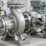
![Industrial centrifugal pump installed on a concrete foundation with precision piping and alignment.]()
How to Use a Pump Installation Checklist for Maximum Reliability
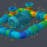
![3D Caesar II pipe stress analysis model of a centrifugal pump piping system showing stress distribution.]()
Pump-Piping Alignment Caesar II Stress Analysis Methodology
![3D render of a structural steel cross-bracing connection with a gusset plate.]()
Mastering Steel Connections with a Cross-Bracing Design Example
![Industrial engineer checking shaft alignment on a centrifugal pump during commissioning.]()
How to Use a Pump Commissioning Checklist for Start-Up