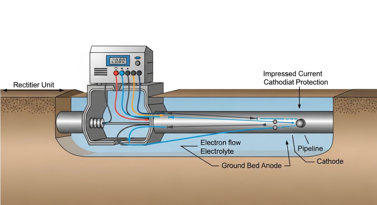
Cathodic Protection: Engineering Principles for Pipeline Integrity
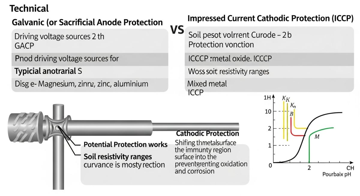
In my two decades of managing cross-country pipeline assets, I have observed that corrosion remains the single most significant threat to structural longevity. Cathodic protection (CP) is not merely an add-on; it is the primary defense mechanism against the inevitable oxidation of ferrous materials in aggressive soil or aqueous environments. By shifting the potential of the pipeline into the immunity region of the Pourbaix diagram, we effectively halt the dissolution of iron atoms.
This guide dissects the technical requirements for implementing robust CP systems. We will move beyond basic theory to explore the specific current density requirements, soil resistivity testing, and the critical balance between galvanic and impressed current systems. Whether you are designing for a new transmission line or retrofitting an aging distribution network, understanding these electrochemical fundamentals is non-negotiable for ensuring long-term asset reliability.
Key Takeaways for Engineers
- Master the electrochemical shift from active corrosion to immunity.
- Differentiate between sacrificial anode and impressed current (ICCP) applications.
- Apply NACE SP0169 standards for effective field implementation.
- Optimize current distribution to prevent over-protection and hydrogen embrittlement.
Technical Fundamentals of Cathodic Protection Design
Electrochemical Corrosion Control: The systematic application of external electrical current to suppress the anodic dissolution of metal, ensuring the structure remains within the cathodic protection potential criteria defined by NACE SP0169.
At the heart of cathodic protection lies the electrochemical cell. Corrosion occurs when an anode, a cathode, an electrolyte, and a metallic path exist simultaneously. By introducing an external source of electrons, we force the entire pipeline surface to act as a cathode. In my experience, the most common error in design is failing to account for the soil resistivity profile, which dictates the current demand required to achieve the -850 mV (CSE) polarized potential criterion.
Calculating Current Demand
To determine the total current requirement (I), we use the formula I = A x J x (1 – E), where A is the surface area of the bare metal, J is the current density required for the specific environment, and E is the coating efficiency. For a well-coated pipeline, E may reach 99%, but I always design for a conservative 95% to account for coating degradation over a 20-year service life.
Field Warning: Hydrogen Embrittlement
Over-protection is a genuine risk, particularly for high-strength steels. If the potential becomes too negative (typically more negative than -1100 mV CSE), hydrogen evolution occurs at the cathode surface. This can lead to hydrogen-induced cracking (HIC) or hydrogen embrittlement, effectively compromising the structural integrity of the pipe wall you are trying to protect.
When selecting between Galvanic Anode Cathodic Protection (GACP) and Impressed Current Cathodic Protection (ICCP), the decision is driven by the current demand and the resistivity of the electrolyte. GACP relies on the potential difference between the anode material (magnesium, zinc, or aluminum) and the steel pipe. It is self-regulating and requires no external power, making it ideal for short, well-coated pipelines in low-resistivity soils.
Conversely, ICCP systems utilize an external DC power source (rectifier) to drive current from an inert anode bed to the structure. This allows for much higher current outputs, which is necessary for large-diameter, poorly coated, or bare pipelines. The design of the anode groundbed—whether deep-well or distributed—must be carefully modeled to ensure uniform current distribution and to minimize interference with neighboring metallic structures.
System Performance Evaluation: A comparative analysis of GACP and ICCP methodologies, focusing on operational reliability, maintenance requirements, and long-term economic viability in industrial pipeline networks.
Advantages
- Self-Regulating: Galvanic systems require no external power, eliminating risks from power outages.
- Low Maintenance: Minimal monitoring is required compared to complex ICCP rectifier stations.
- No Interference: Lower driving voltages significantly reduce the risk of stray current interference on adjacent assets.
- Ease of Installation: Simple connection methods allow for rapid deployment in remote or congested areas.
Disadvantages
- Limited Output: Galvanic anodes cannot provide the high current density required for large or bare pipelines.
- Soil Dependency: Performance is strictly limited by soil resistivity; high-resistivity soils render galvanic systems ineffective.
- Anode Consumption: Regular replacement of sacrificial anodes is necessary, increasing long-term operational expenditure.
- Potential Fluctuations: Achieving a stable, uniform potential across long distances is difficult with point-source galvanic anodes.
Industrial Asset Protection: Strategic deployment of cathodic protection systems across diverse sectors to mitigate environmental degradation and ensure compliance with international safety and integrity standards.
Cross-Country Oil and Gas Pipelines
High-pressure transmission lines rely on ICCP systems to maintain integrity over hundreds of miles. By utilizing remote monitoring units (RMUs) connected to rectifiers, operators can adjust current output in real-time to compensate for seasonal soil moisture changes and coating degradation.
Marine Infrastructure and Offshore Platforms
Offshore structures utilize a hybrid approach, often employing sacrificial aluminum anodes for initial protection and ICCP for long-term maintenance. The high conductivity of seawater necessitates precise current distribution modeling to prevent localized corrosion at structural joints and splash zones.
Underground Storage Tank (UST) Facilities
Gas stations and chemical storage facilities utilize galvanic magnesium anodes to protect steel tanks from aggressive backfill materials. This application is critical for preventing environmental contamination and meeting stringent regulatory requirements for leak detection and prevention.
Selecting the correct materials for a cathodic protection system requires a rigorous evaluation of soil resistivity, electrolyte chemistry, and the specific surface area of the structure requiring protection. In my experience, the design phase often fails when engineers overlook the interaction between the anode material and the local environment, leading to premature passivation or excessive consumption rates.
The following table outlines the standard operating ranges and typical applications for common galvanic and impressed current anode materials. These values are derived from NACE International guidelines and represent the baseline for calculating current demand and system longevity. Always verify these parameters against site-specific soil analysis reports before finalizing your bill of materials.
| Anode Material | Typical Potential (V) | Efficiency (%) | Primary Application |
|---|---|---|---|
| High-Potential Magnesium | -1.75 | 50 | High resistivity soils |
| Zinc (ASTM B418) | -1.10 | 90 | Marine/Seawater environments |
| High-Silicon Cast Iron | Variable (ICCP) | N/A | Deep groundbeds |
| Mixed Metal Oxide (MMO) | Variable (ICCP) | N/A | Long-life infrastructure |
Engineers must ensure that the driving voltage of the chosen anode is sufficient to overcome the circuit resistance, including the cable resistance and the anode-to-electrolyte resistance. Failure to account for these variables often results in under-protection of the pipeline, leaving it vulnerable to localized pitting corrosion despite the presence of a system.
The complexity of modern corrosion control systems necessitates a clear understanding of the relationship between electrochemical entities and their respective regulatory frameworks. This matrix maps the critical components of a cathodic protection system to the relevant industry standards, ensuring that every design element remains compliant with global safety and integrity requirements.
By aligning specific hardware components with their corresponding ISO and ASME standards, we create a traceable documentation trail that is essential for both initial commissioning and long-term asset management. This mapping is particularly useful during third-party audits or when transitioning between different regional regulatory jurisdictions.
| Entity | Function | Standard Reference |
|---|---|---|
| Reference Electrode | Potential measurement | ASTM G97 |
| Transformer Rectifier | ICCP power supply | NACE SP0177 |
| Test Station | Monitoring point | ASME B31.8 |
| Isolation Flange | Electrical decoupling | ISO 15589 |
Maintaining this matrix throughout the project lifecycle allows for rapid identification of component failure modes. When a system reading deviates from the expected baseline, referring back to these standard-linked entities helps in isolating whether the issue is electrical, chemical, or mechanical in nature.
Commissioning a cathodic protection system is the final, critical step in ensuring the long-term integrity of buried or submerged assets. In my experience, the difference between a system that lasts thirty years and one that fails in five often comes down to the rigor applied during the initial site verification phase. This checklist serves as a mandatory protocol for field engineers to validate that the installed hardware meets the design intent and complies with NACE SP0169 requirements.
-
01.
Verify electrical continuity across all pipeline joints and mechanical couplings to ensure the entire segment is protected. -
02.
Confirm the isolation of the pipeline from foreign structures, including grounding systems and non-protected metallic piping. -
03.
Measure the native pipe-to-soil potential at all test stations before energizing the system to establish a baseline. -
04.
Inspect all cable connections for mechanical integrity and ensure proper waterproofing of splice kits to prevent moisture ingress. -
05.
Validate the output of the transformer rectifier against the calculated current demand for the specific coating breakdown factor. -
06.
Document the “instant-off” potential readings to eliminate the IR drop error and confirm true polarization levels.
Once these checks are complete, the system must be monitored for a stabilization period of at least 48 hours. Any fluctuations in current output or potential readings during this window should trigger an immediate investigation into potential short circuits or coating defects that were not identified during the initial survey. Proper documentation of these verification steps is essential for regulatory compliance and future maintenance planning.
Problem: Premature Anode Consumption in High-Resistivity Soil
- Rapid depletion of magnesium anodes observed within 18 months of installation.
- Soil resistivity measurements were significantly lower than the initial design survey indicated.
- Unintended electrical contact with a nearby copper grounding grid caused galvanic interference.
- Excessive current demand led to localized coating disbondment at the pipe-anode connection point.
Outcome: System Optimization and Integrity Restoration
- Installed high-impedance isolation kits to decouple the pipeline from the copper grounding system.
- Replaced magnesium anodes with a deep-well ICCP system to provide more controlled current distribution.
- Achieved a consistent polarized potential of -850 mV across the entire 5km pipeline segment.
- Reduced annual maintenance costs by 40% through the implementation of remote monitoring telemetry.
The recommendation for similar projects is to conduct a comprehensive soil resistivity survey at multiple depths before selecting the anode type. Relying on surface-level data often masks the presence of deeper, more corrosive soil strata that can drastically alter the performance of a galvanic system.
What is the difference between GACP and ICCP?
- ICCP is preferred for large, poorly coated, or high-current-demand structures.
- GACP is limited by the driving voltage of the sacrificial metal.
- ICCP allows for adjustable output to compensate for changing environmental conditions.
How do I calculate the required current for a pipeline?
- Calculate surface area using pipe diameter and length.
- Apply a coating breakdown factor based on the age and type of coating.
- Factor in the soil resistivity to determine the necessary driving voltage.
- Consult NACE SP0169 for recommended current density values for different soil types.
What is the significance of the -850 mV criterion?
- It represents the minimum potential required to stop the anodic dissolution of iron.
- Readings must be taken with the current “off” to avoid errors caused by voltage drops in the soil.
- In anaerobic conditions, a more negative potential may be required to prevent sulfate-reducing bacteria activity.
Why is IR drop a concern during potential measurements?
- “Instant-off” measurements are the primary method for eliminating IR drop.
- High soil resistivity increases the magnitude of the IR drop error.
- Modern data loggers can capture the potential decay immediately after the current is interrupted.
How do I prevent interference from other pipelines?
- Perform interference testing whenever a new pipeline is installed near existing infrastructure.
- Use diode-based bonds to allow current flow in only one direction.
- Coordinate with the operators of the foreign system to balance the protection levels.
What is the role of coating in cathodic protection?
- Coatings reduce the total current required to achieve protection.
- Cathodic protection prevents under-film corrosion if the coating is damaged.
- The combination of both methods is the industry standard for long-term pipeline integrity.
📚 Recommended Resources: Cathodic Protection
Read these Guides
- 📄 Comprehensive Guide to Cathodic Protection for Buried Pipelines
- 📄 Aboveground Storage Tanks: Design, Components, and Erection Engineering Guide
- 📄 Managing Geotechnical Risks in Green Hydrogen Infrastructure Projects
- 📄 Geotechnical Considerations for Electrolyzer Facilities: A Foundation Design Guide



Complete Course on
Piping Engineering
Check Now
Key Features
- 125+ Hours Content
- 500+ Recorded Lectures
- 20+ Years Exp.
- Lifetime Access
Coverage
- Codes & Standards
- Layouts & Design
- Material Eng.
- Stress Analysis
