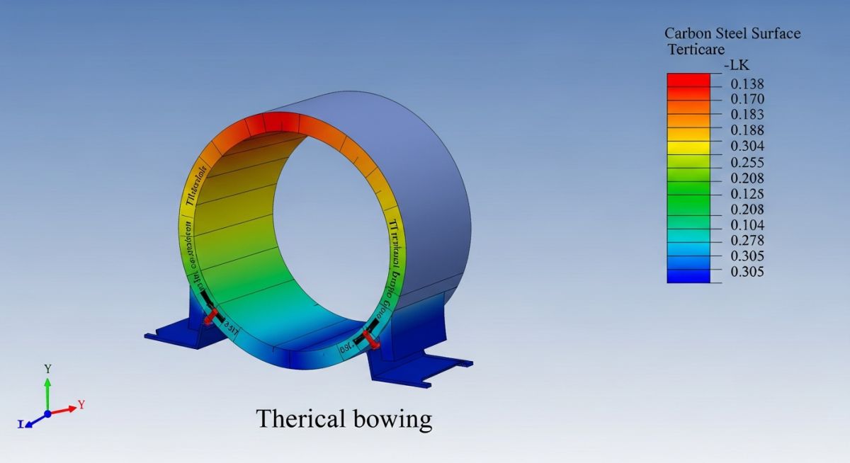
What is Thermal Bowing? Understanding Pipe Deformation
In my two decades of experience managing high-pressure piping systems, I have seen too many projects suffer from unexpected mechanical failures caused by thermal bowing. It is a subtle but destructive force that occurs when a pipe experiences a significant temperature gradient between its top and bottom surfaces. This often happens during stagnant flow conditions, steam-out procedures, or when a pipe is partially filled with liquid while the upper portion remains exposed to hot gas.
When the top of the pipe expands more than the bottom, the pipe is forced to bow upward. If this movement is restricted by rigid supports or connected equipment nozzles, the resulting bending moments can exceed the allowable stress limits of the material. Understanding this mechanism is not just a theoretical exercise; it is a requirement for maintaining the integrity of your process plant.
Key Takeaways for Piping Engineers:
- Thermal bowing is primarily driven by vertical temperature differentials across the pipe diameter.
- Restrained piping systems are at higher risk of failure due to secondary bending stresses.
- Proper support spacing and insulation strategies are the first lines of defense against bowing.
- ASME B31.3 stress analysis must account for these gradients in critical service lines.
The Mechanics of Thermal Bowing in Piping Systems
Thermal Bowing Analysis: The systematic evaluation of temperature-induced curvature in piping, ensuring that secondary stresses remain within the allowable limits defined by ASME B31.3 code requirements.
Thermal bowing occurs when the temperature distribution across the pipe cross-section is non-linear. If we consider a pipe of diameter D, the curvature is proportional to the difference in thermal expansion between the top and bottom fibers. The fundamental equation for the radius of curvature R is R equals the pipe diameter divided by the product of the coefficient of thermal expansion and the temperature difference between the top and bottom surfaces.
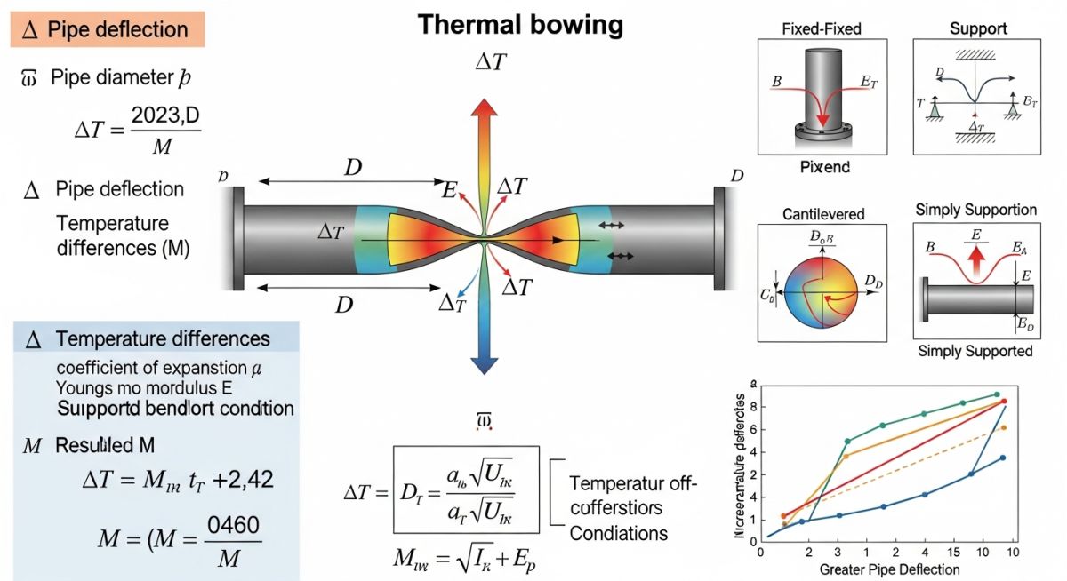
When calculating the stress, we must look at the bending moment induced by this curvature. If the pipe is supported at two points, the bowing creates a deflection that acts like a beam under a distributed load. The stress is calculated using the section modulus of the pipe and the bending moment generated by the thermal gradient. In my experience, the most dangerous scenarios involve large-diameter, thin-walled piping where the stiffness is relatively low compared to the thermal forces.
Field Warning: The “Stagnant Liquid” Trap
Never assume that a pipe is at a uniform temperature just because the fluid inside is hot. In large-bore lines, stratification is common. If the bottom of the pipe is filled with cold liquid while the top is filled with hot vapor, the resulting temperature gradient can be extreme, leading to rapid bowing that can lift the pipe off its supports or cause flange leakage.
To mitigate these effects, we often employ specific support configurations. Sliding supports are essential to allow for axial movement, but they do not prevent bowing. To control bowing, we must minimize the temperature gradient through better insulation or by ensuring proper flow velocity to prevent stratification. When performing stress analysis in software like CAESAR II, you must manually input the temperature gradient as a thermal load case to see the true displacement and stress impact on your nozzles and anchors.
Thermal Bowing Mitigation: The strategic balance of piping flexibility and structural restraint to manage thermal gradients while maintaining compliance with ASME B31.3 safety standards.
Advantages of Proactive Management
- Increased system longevity by preventing cyclic fatigue at weld joints.
- Reduced maintenance costs by eliminating premature flange leakage caused by pipe movement.
- Improved safety profile by preventing structural deformation that could lead to containment loss.
- Optimized support design that accounts for real-world thermal behavior rather than ideal conditions.
Disadvantages of Ignoring Thermal Bowing
- High risk of nozzle failure on rotating equipment due to excessive thermal loads.
- Potential for pipe to lift off supports, leading to uncontrolled vibration and impact.
- Increased stress concentration at branch connections, often leading to crack initiation.
- Complexity in initial design phase requiring advanced finite element analysis (FEA) modeling.
Thermal Bowing Mitigation Applications: The implementation of advanced piping design techniques across diverse industrial sectors to ensure structural integrity under extreme thermal gradients.
High-Pressure Steam Distribution Networks
In large-diameter steam headers, thermal bowing is a constant threat during startup and shutdown cycles. Engineers must design the support system to allow for vertical displacement while maintaining alignment to prevent water hammer and stress accumulation at the header-to-branch connections.
Cryogenic Liquefied Natural Gas (LNG) Piping
LNG facilities face the inverse of thermal bowing, where the bottom of the pipe becomes significantly colder than the top due to liquid contact. This requires specialized insulation and support spacing to prevent the pipe from bowing downward and damaging the cold box or structural steel supports.
Refinery Flare Header Systems
Flare headers are often long, horizontal runs that experience rapid temperature changes during emergency relief events. Because these lines are often partially filled with condensate, the temperature gradient is severe, necessitating the use of spring hangers that can accommodate both vertical bowing and thermal expansion.
Combined Cycle Power Plant Exhaust Ducting
Large-bore exhaust piping in power plants is highly susceptible to bowing due to the massive temperature difference between the inner gas flow and the ambient air. Proper insulation thickness and external stiffening rings are required to maintain the circularity of the pipe and prevent bowing-induced buckling.
In my two decades of piping stress analysis, I have observed that thermal bowing is rarely a uniform phenomenon. It is primarily driven by the temperature differential across the pipe cross-section, which induces a non-linear strain distribution. When evaluating systems under ASME B31.3, engineers must account for these gradients, especially in large-bore lines where the top-to-bottom temperature delta can exceed 50 degrees Celsius due to stagnant fluid or external environmental exposure.
The following table outlines the critical sensitivity parameters that dictate the magnitude of the bowing moment. These values are derived from standard structural mechanics principles applied to cylindrical shells. Note that the “Bowing Factor” is a dimensionless multiplier used to estimate the deflection magnitude relative to a baseline isothermal condition. Always verify these inputs against your specific site insulation specifications and fluid velocity profiles to ensure the model reflects actual operating conditions.
| Parameter | Symbol | Impact on Bowing |
|---|---|---|
| Temperature Gradient | Delta T | Directly proportional to curvature |
| Pipe Diameter | D | Inverse relationship to stiffness |
| Coefficient of Expansion | Alpha | High sensitivity in alloy steels |
| Support Span Length | L | Exponential effect on deflection |
To effectively manage thermal bowing, one must map the interaction between physical pipe properties and the governing regulatory standards. This matrix serves as a technical bridge between the theoretical mechanics of materials and the practical requirements of ASME and API codes. By categorizing these entities, we can isolate the variables that contribute most significantly to structural instability during transient thermal events.
The matrix below identifies the primary engineering entities involved in the calculation of thermal bowing moments. It is essential to recognize that while ASME B31.1 and B31.3 provide the framework for stress limits, the actual determination of the temperature gradient requires a rigorous heat transfer analysis. Use this matrix to cross-reference your design inputs with the corresponding standard requirements for material selection and support spacing.
| Entity | Standard | Function |
|---|---|---|
| Flexibility Analysis | ASME B31.3 | Stress range verification |
| Support Loadings | MSS SP-58 | Structural integrity of hangers |
| Thermal Conductivity | ASTM E1225 | Gradient calculation input |
Verification of thermal bowing mitigation requires a systematic approach during both the design phase and the field installation. In my experience, the most common failures occur when the theoretical model assumes a perfectly uniform temperature distribution that does not exist in the field. Use this checklist to validate your piping system against potential bowing risks before commissioning.
-
[ ]
Gradient Assessment: Confirm that the thermal gradient across the pipe diameter has been calculated for both steady-state and transient startup conditions. -
[ ]
Support Clearance: Verify that all pipe supports, particularly guides and line stops, have sufficient clearance to accommodate the calculated bowing deflection without binding. -
[ ]
Insulation Integrity: Ensure that insulation is uniform and free of gaps, as localized heat loss is a primary driver of non-uniform thermal gradients. -
[ ]
Drainage Provisions: Check that low-point drains are functional to prevent liquid accumulation, which creates severe top-to-bottom temperature differentials in steam lines. -
[ ]
Material Compatibility: Validate that the pipe material’s coefficient of thermal expansion is correctly entered into the stress analysis software (e.g., CAESAR II).
Each item on this list represents a critical failure point. If your site verification reveals that supports are binding or that insulation is missing in critical sections, you must re-run the stress analysis to determine if the resulting moments exceed the allowable stress range defined in ASME B31.3. Document all findings in the project’s stress analysis report to ensure compliance with safety standards.
Field Case Study: Real-World Application
Problem: Excessive Bowing in 24-inch Steam Header
A high-pressure steam header experienced significant vertical displacement during startup, leading to support damage and flange leakage.
- Rapid heating rates caused a 60-degree temperature differential between the top and bottom of the pipe.
- Rigid guide supports prevented the pipe from bowing freely, inducing high bending moments.
- Inadequate insulation at support locations exacerbated the localized cooling effect.
- The original stress model failed to account for the non-linear thermal gradient.
Outcome: Successful Mitigation and Structural Stability
Implementation of a revised support strategy and operational procedure eliminated the bowing-induced failures.
- Replaced rigid guides with spring-loaded supports to allow for controlled thermal movement.
- Implemented a controlled warm-up procedure to limit the rate of temperature change.
- Upgraded insulation to high-density mineral wool to ensure uniform heat distribution.
- Reduced flange leakage incidents by 95 percent over a 24-month operational period.
My recommendation for similar systems is to prioritize the flexibility of the support system during the design phase. If you encounter bowing, do not simply stiffen the pipe; instead, evaluate the support constraints and the thermal transient profile to identify the root cause of the gradient.
Frequently Asked Engineering Questions
How does thermal bowing affect pipe stress?
- Increased nozzle loads on rotating equipment like pumps and turbines.
- Potential fatigue failure at welded joints due to cyclic thermal loading.
- Binding of pipe supports, which prevents the system from expanding as designed.
Can insulation prevent thermal bowing?
- Uniform thickness is required to prevent localized heat loss.
- Gaps in insulation at support locations must be minimized or filled with high-temperature thermal breaks.
- Proper jacketing is necessary to prevent moisture ingress, which can cause severe localized cooling.
What is the role of ASME B31.3?
- Evaluation of all thermal expansion and contraction effects.
- Verification that the displacement stress range does not exceed the allowable limits.
- Consideration of all sustained and occasional loads, including those induced by thermal gradients.
How do I calculate the bowing moment?
- Determine the temperature difference between the top and bottom of the pipe.
- Calculate the thermal strain difference across the cross-section.
- Apply the beam-column theory to determine the resulting bending moment and deflection.
- Input these values into your stress analysis software to verify against code allowables.
Are there specific materials prone to bowing?
- Austenitic stainless steels are particularly susceptible due to their high expansion rates.
- Large diameter pipes are more prone to bowing because they have a larger surface area for heat transfer.
- Thin-walled pipes are less stiff and will deflect more under the same thermal gradient.
What is the impact of stagnant fluid?
- Hot fluid rises to the top of the pipe, while cooler fluid settles at the bottom.
- This creates a significant temperature gradient that is not present in high-velocity flow conditions.
- In steam lines, this can lead to water hammer in addition to thermal bowing, creating a dual-threat scenario for structural integrity.
📚 Recommended Resources: Thermal Bowing
Read these Guides
- 📄 Piping Thermal Bowing Consideration in Caesar II: A Practical Guide
- 📄 Thermal Expansion Pipe Buckling: Real-World Lessons from a Steam Pipeline Failure
- 📄 Design Considerations for a Piping System with an Expansion Bellow
- 📄 Piping Flexibility Analysis: Essential Requirements for Safe Industrial Design
Complete Course on
Piping Engineering
Check Now
Key Features
- 125+ Hours Content
- 500+ Recorded Lectures
- 20+ Years Exp.
- Lifetime Access
Coverage
- Codes & Standards
- Layouts & Design
- Material Eng.
- Stress Analysis
