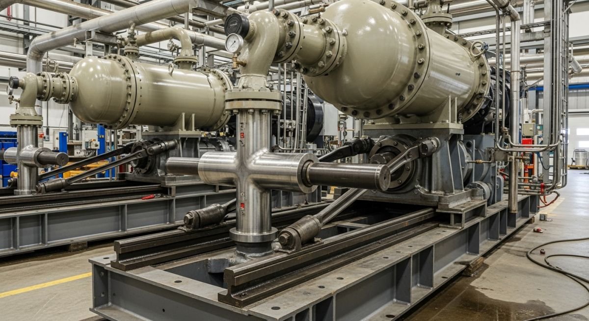
Basics of Reciprocating Compressor Design and Selection
In my two decades of field experience, I have observed that the choice between a reciprocating compressor and a rotary compressor often dictates the long-term reliability of an entire process plant. While rotary units offer simplicity, the reciprocating compressor remains the workhorse for high-pressure, low-flow applications where efficiency is non-negotiable.
Understanding the mechanical nuances—from piston rod loading to valve dynamics—is critical for any piping engineer tasked with skid layout or pulsation control. This guide breaks down the fundamental differences, ensuring your next installation meets the rigorous demands of modern industrial gas compression.
Key Takeaways
- Reciprocating compressors excel in high-pressure, low-flow gas services.
- API 618 governs reciprocating units, focusing on pulsation and vibration control.
- Rotary compressors (API 619) are preferred for continuous, high-volume, lower-pressure applications.
- Piping design must account for the inherent discharge pulsations of reciprocating machines.
Technical Analysis of the Reciprocating Compressor
Reciprocating Compressor Engineering: The application of thermodynamic principles and mechanical design standards to manage gas compression cycles through piston-driven displacement within a cylinder, strictly governed by API 618 for safety and performance.
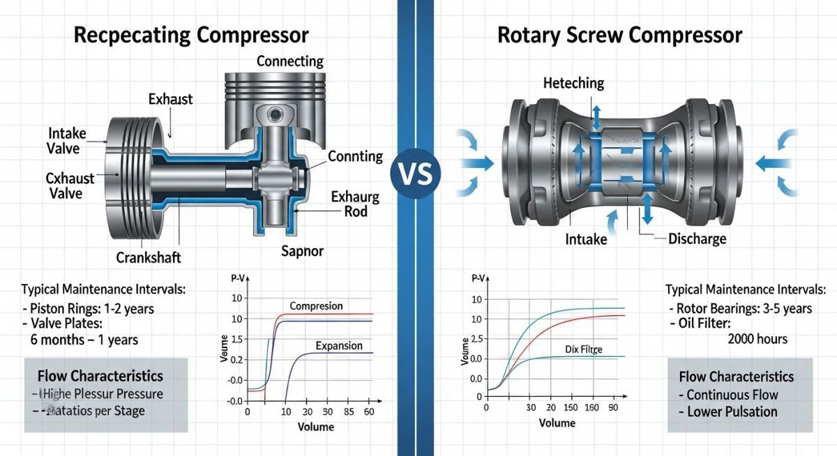
The reciprocating compressor operates on the principle of positive displacement. A piston moves within a cylinder, drawing gas through suction valves and compressing it through discharge valves. Unlike rotary machines, this process is inherently intermittent, creating pressure pulsations that require careful piping design and the use of suction and discharge dampeners.
Thermodynamic and Mechanical Stress Parameters
When calculating the required power for a reciprocating compressor, we utilize the polytropic compression formula. The work done per cycle is a function of the pressure ratio and the gas properties, specifically the ratio of specific heats (k). In my experience, the most critical design constraint is the rod load—the force exerted on the piston rod during the compression stroke.
Engineers must ensure that the combined inertial and pressure forces do not exceed the manufacturer’s rated rod load. If the rod load is exceeded, fatigue failure of the crosshead or the piston rod becomes inevitable. We reference API 618 to determine the allowable limits for these cyclic loads.
Field Warning: Pulsation Induced Vibration
Reciprocating compressors generate significant acoustic energy. If the piping natural frequency aligns with the compressor’s operating frequency or its harmonics, severe vibration occurs. Always perform a pulsation study (API 618, Section 7) to verify that piping supports and dampener volumes are correctly sized to mitigate these risks.
Design Limitations and Standards
The design of the cylinder cooling system is another area where many projects falter. High compression ratios lead to elevated discharge temperatures, which can degrade lubricating oils and damage valve components. We typically limit discharge temperatures to 150 degrees Celsius to prevent gas decomposition or polymerization.
Furthermore, the valve design is the heart of the compressor. Plate valves or poppet valves must be selected based on the gas molecular weight and the required speed of the machine. High-speed machines require lightweight valves to minimize inertia, whereas low-speed, heavy-duty machines can utilize more robust, traditional valve designs.
Compressor Performance Tradeoffs: A technical evaluation of the operational efficiency, maintenance requirements, and mechanical limitations inherent in reciprocating versus rotary compression technologies for industrial gas processing.
Advantages of Reciprocating Units
- Superior efficiency at high pressure ratios compared to rotary screw designs.
- Ability to handle varying gas compositions and molecular weights effectively.
- Lower power consumption for low-flow, high-pressure applications.
- Proven longevity in harsh, corrosive, or dirty gas environments.
- Modular design allows for easy capacity control via clearance pockets.
Disadvantages of Reciprocating Units
- High maintenance frequency due to sliding wear on valves and rings.
- Significant discharge pulsations requiring complex piping dampener systems.
- Higher initial capital expenditure for foundation and pulsation control.
- Increased footprint and weight compared to rotary screw compressors.
- Complex lubrication systems required for cylinder and rod packing.
Industrial Compression Deployment: Strategic implementation of reciprocating and rotary compressor technologies across diverse sectors, optimized for specific pressure, flow, and gas purity requirements.
Natural Gas Pipeline Transmission
Reciprocating compressors are the standard for high-pressure pipeline boosting where gas must be moved over long distances. Their ability to handle high compression ratios ensures that gas remains at the required pressure despite significant friction losses in the pipeline network.
Hydrogen Refueling Stations
In the emerging hydrogen economy, reciprocating compressors are essential for achieving the ultra-high pressures (up to 900 bar) required for vehicle fueling. Their positive displacement nature allows for precise control of gas density, which is critical for accurate mass flow metering during the dispensing process.
Petrochemical Feedstock Compression
Refineries utilize reciprocating units for handling process gases that vary in molecular weight and composition. These machines provide the flexibility to adjust capacity through clearance pockets, ensuring the compressor can adapt to changing feedstock demands without requiring a complete system overhaul.
Selecting the appropriate compression technology requires a granular understanding of how mechanical design influences thermodynamic efficiency. In my experience, the choice between a reciprocating compressor and a rotary unit is rarely about cost alone; it is fundamentally about the pressure-flow envelope and the specific gas properties involved in your process loop.
The following table outlines the critical performance parameters that dictate selection. Reciprocating units, governed by API 618, excel in high-pressure, low-flow applications where volumetric efficiency must be maintained across varying suction conditions. Conversely, rotary compressors, often designed to API 619 standards for screw-type machines, provide a continuous, pulse-free flow that is ideal for high-volume, moderate-pressure process gas applications.
| Parameter | Reciprocating (API 618) | Rotary (API 619) |
|---|---|---|
| Pressure Ratio | High (up to 1000+ bar) | Moderate (up to 25-30 bar) |
| Flow Characteristics | Pulsating / Intermittent | Continuous / Smooth |
| Maintenance Interval | Frequent (Valves/Rings) | Extended (Bearings/Seals) |
| Gas Composition | Dry / Clean Gases | Wet / Dirty / Polymerizing |
Engineers must note that reciprocating units require significant pulsation dampening infrastructure to protect downstream piping from fatigue. Rotary units, while quieter and more compact, are highly sensitive to liquid carryover and require precise oil-injection management to maintain internal sealing clearances.
To effectively manage a compression project, one must map the physical hardware to the governing regulatory standards. This matrix serves as a technical reference for identifying the intersection between mechanical components and the relevant industry codes that ensure operational safety and mechanical integrity.
When reviewing vendor documentation, I always cross-reference the equipment class against these specific standards. Misalignment here often leads to premature component failure, particularly in the sealing systems and valve assemblies where the mechanical stress is highest during the compression cycle.
| Entity | Standard | Primary Function |
|---|---|---|
| Reciprocating Compressor | API 618 | Positive displacement gas compression |
| Rotary Screw Compressor | API 619 | Continuous rotary gas compression |
| Piping Pulsation | API 618 Annex | Acoustic resonance mitigation |
| Mechanical Seals | API 682 | Shaft sealing and leakage control |
This matrix highlights that while the hardware differs, the engineering rigor applied to both remains consistent. Whether you are dealing with the reciprocating piston rings or the rotary screw rotors, the focus remains on maintaining the integrity of the pressure boundary under cyclic loading conditions.
Commissioning a reciprocating compressor requires a disciplined approach to site verification. In my years of field experience, I have found that most startup failures stem from overlooked piping support issues or improper lubrication system calibration. Use this checklist to ensure your installation meets the stringent requirements of API 618.
-
[ ]
Pulsation Dampener Alignment: Verify that all dampeners are supported independently of the compressor cylinder to prevent nozzle fatigue. -
[ ]
Lubrication System Flow: Confirm that the force-feed lubricator is delivering the correct oil volume to each cylinder bore and packing case. -
[ ]
Foundation Grouting: Ensure the compressor frame is level and the grout has achieved the specified compressive strength before final bolt torquing. -
[ ]
Suction Scrubber Integrity: Inspect the suction scrubber for debris and verify that the high-level switch is functional to prevent liquid carryover. -
[ ]
Piping Thermal Expansion: Check that piping loops allow for thermal growth without imposing excessive nozzle loads on the compressor casing.
Before final handover, perform a full-load test run to monitor vibration levels at the crosshead and main bearings. Any deviation from the baseline vibration signature defined in the API 618 documentation must be investigated immediately to prevent catastrophic mechanical failure during the first 500 hours of operation.
The Problem: Excessive Piping Vibration
A mid-stream gas facility reported severe piping vibration on the discharge side of a multi-stage reciprocating compressor, leading to repeated flange leaks.
- Acoustic resonance occurring at the third harmonic of the compressor speed.
- Inadequate stiffness in the discharge piping support structure.
- Pulsation dampener volume was undersized for the actual gas molecular weight.
- Flange bolts were loosening due to cyclic fatigue loading.
The Outcome: Successful Mitigation
By implementing a comprehensive pulsation study and structural modification, we restored system integrity.
- Installed an orifice plate at the dampener nozzle to dampen acoustic energy.
- Added secondary structural steel supports to increase piping natural frequency.
- Reduced vibration amplitude by 75 percent, well within API 618 limits.
- Eliminated flange leaks and extended the mean time between maintenance.
My recommendation for similar sites is to conduct a formal pulsation analysis during the FEED stage. Relying on standard piping design without accounting for the specific acoustic signatures of reciprocating machines is a common oversight that leads to significant operational downtime.
Frequently Asked Engineering Questions
Why is API 618 critical for reciprocating compressors?
API 618 serves as the global benchmark for the design, material selection, and testing of reciprocating compressors in the oil and gas industry. It ensures that equipment can withstand the extreme cyclic stresses inherent in positive displacement compression.
- Defines strict limits for pulsation and vibration to prevent piping fatigue.
- Standardizes the testing procedures for mechanical performance and gas throughput.
- Provides a framework for safety-critical components like piston rods and crossheads.
- Ensures interoperability between the compressor and the process piping system.
What are the primary differences between API 618 and API 619?
The fundamental difference lies in the compression mechanism: API 618 covers reciprocating (piston) compressors, while API 619 covers rotary screw compressors. These standards address vastly different mechanical challenges.
- API 618 focuses on managing intermittent flow and high-pressure ratios.
- API 619 focuses on continuous flow and the management of internal oil-flooded rotors.
- Reciprocating units require pulsation dampeners; rotary units require oil separation systems.
- Maintenance cycles for reciprocating units are driven by valve wear, whereas rotary units are driven by bearing and seal life.
How do I mitigate pulsation in reciprocating piping?
Pulsation mitigation is a multi-layered engineering process that begins with a formal acoustic simulation. You must address the source of the pressure waves before they propagate into the piping network.
- Install pulsation dampeners as close to the cylinder nozzles as possible.
- Use orifice plates to create pressure drops that dissipate acoustic energy.
- Increase the stiffness of piping supports to shift the natural frequency away from the compressor speed.
- Optimize the piping layout to minimize the number of elbows and dead-legs that can act as acoustic resonators.
What is the role of the suction scrubber?
The suction scrubber is the primary defense against liquid ingestion in reciprocating compressors. Because liquids are incompressible, any liquid entering the cylinder will cause immediate mechanical failure, such as broken valves or bent connecting rods.
- Separates entrained liquids and solids from the incoming gas stream.
- Provides a buffer volume to handle sudden liquid slugs.
- Equipped with level switches that trigger an emergency shutdown (ESD) if liquid levels exceed safe limits.
- Essential for maintaining the longevity of the piston rings and cylinder liners.
When should I choose a rotary compressor?
Rotary compressors are the preferred choice when your process requires a steady, pulse-free flow of gas at moderate pressures. They are particularly effective in applications where the gas composition might be variable or contain trace amounts of liquids.
- Ideal for high-volume process gas applications where reciprocating units would be too large.
- Better suited for gases that may polymerize or contain contaminants.
- Lower footprint and reduced foundation requirements compared to reciprocating units.
- Easier to integrate into automated control systems due to the continuous nature of the compression cycle.
How do I manage thermal expansion in compressor piping?
Managing thermal expansion is critical to preventing nozzle loads that exceed the manufacturer’s allowable limits. In my experience, the most effective approach is to design flexible piping loops that accommodate growth without relying on the compressor casing for support.
- Perform a formal pipe stress analysis using software like CAESAR II.
- Use spring hangers to support the weight of the piping while allowing for thermal movement.
- Ensure that expansion joints are used only when necessary and are properly anchored.
- Verify that the piping layout allows for cold-springing if required by the stress analysis results.
📚 Recommended Resources: Reciprocating Compressor
Read these Guides
- 📄 Centrifugal vs Reciprocating Compressor: The Ultimate Industrial Engineering Guide
- 📄 Reciprocating Compressor Sizing Guide: API 618 Engineering Standards (2026)
- 📄 Shaft Alignment Methodology for Compressor and Driver Systems
- 📄 Centrifugal Compressors: Engineering Design Guidelines and Industrial Applications
🎓 Advanced Training



Complete Course on
Piping Engineering
Check Now
Key Features
- 125+ Hours Content
- 500+ Recorded Lectures
- 20+ Years Exp.
- Lifetime Access
Coverage
- Codes & Standards
- Layouts & Design
- Material Eng.
- Stress Analysis
