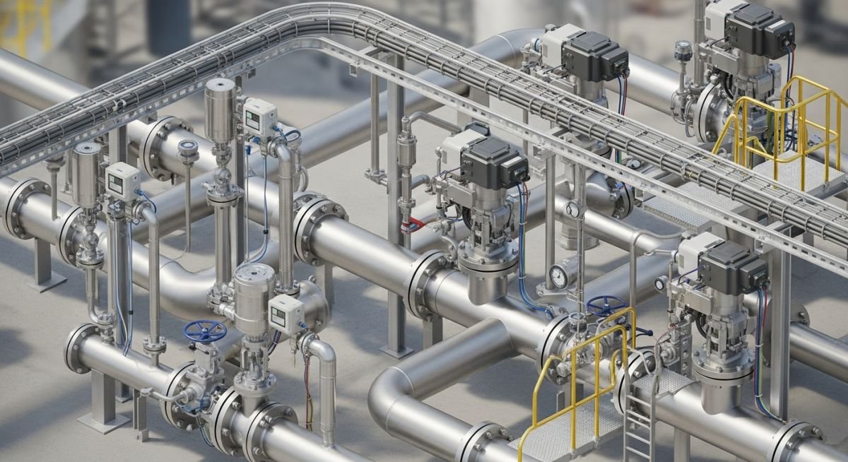
Overview of Piping and Instrument Interface for Plant Design
In my two decades of field experience, I have observed that the most frequent cause of project delays and costly rework is a disconnect between the piping design team and the instrumentation group. The Piping and Instrument Interface is not merely a drafting exercise; it is the backbone of plant safety and process control. When we fail to align the physical piping requirements—such as thermowell insertion lengths or control valve clearance—with the process control logic, we compromise the integrity of the entire facility.
This guide explores the critical intersection of ASME B31.3 piping codes and ISA 5.1 instrumentation standards. We will examine how to manage instrument tap locations, branch connections, and the physical constraints of inline devices to ensure your plant design remains both maintainable and compliant.
Key Takeaways for Engineering Teams:
- Mastering the physical integration of control valves and flow meters.
- Ensuring compliance with ASME B31.3 for instrument branch connections.
- Optimizing P&ID accuracy to prevent field-level installation conflicts.
- Reducing maintenance downtime through strategic instrument placement.
Technical Analysis of Piping and Instrument Interface
Piping and Instrument Interface Design: The technical coordination of physical piping geometry with instrumentation requirements to satisfy process control, safety, and maintenance standards.
The interface between piping and instrumentation is governed by the need to maintain process fluid integrity while providing accurate data to the control system. When designing these interfaces, I always start by evaluating the branch connection requirements defined in ASME B31.3. For instrument taps, the use of weldolets or threadolets must be carefully calculated based on the pipe wall thickness and the pressure-temperature rating of the process fluid.
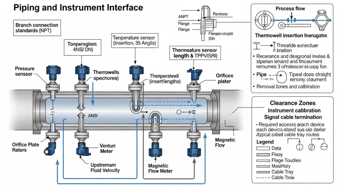
Managing Instrument Tap Stress and Geometry
One of the most critical aspects of the Piping and Instrument Interface is the structural integrity of the branch connection. When an instrument tap is installed on a high-pressure line, the stress concentration factor at the junction can lead to fatigue failure if not properly reinforced. I recommend performing a formal stress analysis for any tap larger than 1 inch on high-vibration lines.
Field Warning: Thermowell Insertion Depth
Always verify the thermowell insertion length against the pipe diameter. If the thermowell extends too far, it can induce vortex-induced vibration (VIV), leading to catastrophic failure of the instrument or the pipe wall. Refer to ASME PTC 19.3 TW for wake frequency calculations.
Control Valve and Flow Meter Integration
Control valves require specific upstream and downstream straight-run piping to ensure laminar flow and accurate control. In my experience, failing to account for these requirements during the initial P&ID development leads to significant field modifications. For orifice plates, the ISO 5167 standard dictates the minimum straight pipe lengths required before and after the device to prevent flow disturbances.
When integrating these devices, we must also consider the weight of the instrumentation. Large control valves often require independent pipe supports to prevent excessive bending moments on the piping system. I calculate the total moment (M) at the flange connection using the formula M = F * L, where F is the force exerted by the valve weight and L is the distance from the pipe centerline to the valve center of gravity.
Interface Optimization Benefits and Risks: A balanced assessment of the technical and operational trade-offs inherent in integrated piping and instrumentation design strategies.
Advantages
- Enhanced process control accuracy through optimized sensor placement.
- Reduced field rework by identifying spatial conflicts during 3D modeling.
- Improved safety compliance by adhering to ASME B31.3 branch standards.
- Lower long-term maintenance costs via accessible instrument mounting.
- Better data reliability for plant-wide automation systems.
Disadvantages
- Increased initial engineering hours for detailed interface coordination.
- Higher complexity in piping stress analysis due to added branch weights.
- Potential for increased leak paths if instrument connections are poorly specified.
- Strict adherence to standards can limit flexibility in tight plant layouts.
- Requires high-level cross-disciplinary communication between piping and I&C teams.
Industrial Interface Implementation: Practical deployment scenarios where rigorous piping and instrument integration is required for safe and efficient plant operations.
High-Pressure Steam Distribution
In power generation, the interface between steam piping and pressure transmitters is critical. We must utilize siphon loops to protect instrumentation from high-temperature steam while ensuring the piping branch connection meets the high-pressure requirements of ASME B31.1.
Cryogenic Liquefied Natural Gas (LNG) Plants
Managing the interface in cryogenic service requires specialized materials and thermal expansion loops. Instrumentation must be mounted to allow for extreme contraction of the piping system without stressing the process connections or causing seal failures.
Refinery Hydrocracker Units
Hydrocracker units involve high-temperature, high-pressure hydrogen service where instrument tap integrity is paramount. We implement double-block-and-bleed configurations at the piping interface to allow for safe instrument maintenance without shutting down the main process line.
Effective integration of process piping and instrumentation requires a rigorous adherence to standardized design parameters. When I review P&ID layouts, I focus on the physical interface points where the piping system meets the instrument tapping points, thermowell installations, and control valve assemblies. These interfaces are not merely connection points; they are critical stress concentration areas that must be evaluated under ASME B31.3 for pressure integrity and ISA 5.1 for functional instrumentation logic.
The following table outlines the standard interface requirements for common instrumentation components. These values represent the minimum design considerations I apply during the 30% and 60% model review stages to ensure that instrument maintenance access does not compromise the structural integrity of the piping system. Note that these parameters are subject to specific fluid service conditions and must be verified against the project-specific piping material specification (PMS).
| Component | Interface Standard | Primary Concern |
|---|---|---|
| Thermowell | ASME PTC 19.3 TW | Wake frequency and vibration |
| Control Valve | ISA 75.01 | Flow capacity and cavitation |
| Pressure Tap | ASME B31.3 | Branch connection reinforcement |
| Flow Meter | ISO 5167 | Upstream/downstream straight run |
By maintaining these interface standards, we minimize the risk of premature fatigue failure at instrument nozzles. Always ensure that the piping stress analysis team is provided with the exact weight and center of gravity for heavy instrumentation, such as large control valves or flow meters, to prevent piping misalignment during thermal expansion cycles.
The complexity of modern plant design necessitates a clear mapping between mechanical piping components and their corresponding instrumentation control logic. In my experience, the most frequent design errors occur when the piping team and the instrumentation team operate in silos, leading to mismatched flange ratings or incompatible material compatibility for wetted parts. This matrix serves as a cross-reference tool to align these disciplines during the FEED and detailed engineering phases.
This mapping matrix identifies the primary technical entities involved in the Piping and Instrument Interface. By standardizing these relationships, we ensure that every instrument tapping point is documented in the piping isometric drawings and that the instrumentation data sheets reflect the actual piping material specifications. This alignment is vital for procurement accuracy and site construction efficiency.
| Entity | Acronym | Standard Reference |
|---|---|---|
| Piping and Instrumentation Diagram | P&ID | ISA 5.1 |
| Process Piping Code | ASME B31.3 | ASME B31.3 |
| Control Valve Sizing | CVS | ISA 75.01 |
| Thermowell Design | TWD | ASME PTC 19.3 |
Use this matrix to audit your project documentation. If an entity listed here does not have a corresponding standard reference in your project’s design basis, it represents a potential gap in your quality management system that should be addressed before the final design review.
Verification of the Piping and Instrument Interface during the construction and commissioning phase is the final line of defense against operational failure. I have developed this checklist to ensure that the physical installation matches the design intent, specifically focusing on accessibility, orientation, and structural support requirements. Use this during site walkdowns to validate that all ASME B31.3 requirements have been met at the instrument connection points.
-
Orientation Check: Verify that pressure gauges and transmitters are installed in the correct orientation for readability and maintenance access as per ISA 5.1. -
Support Integrity: Confirm that all heavy instrumentation, such as control valves, are independently supported to prevent excessive bending moments on the piping flanges. -
Thermowell Insertion: Ensure the thermowell length is correct for the pipe diameter and that the tip is positioned in the center one-third of the flow stream. -
Material Verification: Cross-reference the wetted parts of the instrument with the piping material specification to prevent galvanic corrosion or chemical incompatibility. -
Clearance Validation: Check that there is sufficient clearance for removing instruments for calibration without requiring the removal of adjacent piping spools.
If any of these items fail verification, document the deviation immediately. In my experience, correcting an interface issue during the construction phase is significantly cheaper than performing a hot-tap or a system shutdown to rectify an instrument installation error after the plant has been commissioned.
The Problem: Premature Thermowell Failure
A high-pressure steam line experienced repeated thermowell failures, leading to process leaks and unplanned downtime.
- The thermowell design did not account for the high-velocity steam flow, causing vortex-induced vibration.
- The piping layout placed the thermowell too close to a downstream elbow, creating turbulent flow conditions.
- The material selection for the thermowell was incompatible with the high-temperature steam chemistry.
- The installation lacked proper support, allowing the vibration to transfer directly to the piping nozzle.
The Outcome: Optimized Interface Design
We successfully resolved the issue by redesigning the interface to meet modern standards.
- Redesigned the thermowell using ASME PTC 19.3 TW wake frequency calculations to ensure structural stability.
- Relocated the thermowell to a straight pipe section with sufficient upstream and downstream distance.
- Upgraded the thermowell material to a high-nickel alloy to resist thermal fatigue and corrosion.
- Implemented a reinforced nozzle design to handle the dynamic loads identified during the stress analysis.
My recommendation is to always perform a wake frequency calculation for any thermowell installation in high-velocity fluid services. Never assume that a standard thermowell length is appropriate for all piping diameters; the fluid dynamics at the interface are unique to every installation point.
Frequently Asked Engineering Questions
How does ISA 5.1 influence piping design?
ISA 5.1 provides the standardized symbols and identification for instrumentation, which directly dictates how piping designers place instrument tapping points on the P&ID. By following this standard, we ensure that:
- The functional requirements of the control loop are clearly communicated to the piping team.
- Instrument locations are optimized for both process control accuracy and physical maintenance access.
- The piping isometric drawings correctly reflect the required instrument connections, preventing field-run errors.
What is the role of ASME B31.3 in instrument nozzles?
ASME B31.3 governs the pressure integrity of the piping system, including all branch connections used for instrumentation. When we add a pressure tap or a thermowell nozzle, we are creating a branch connection that must be evaluated for:
- Pressure reinforcement requirements to maintain the structural integrity of the header pipe.
- Weld quality and inspection standards for the instrument nozzle attachment.
- Compatibility of the branch connection material with the main piping material specification.
How do I handle heavy control valves in piping?
Heavy control valves introduce significant bending moments and potential for vibration that can compromise piping integrity. My approach involves:
- Providing independent structural support for the valve body to isolate it from the piping system.
- Including the valve weight and center of gravity in the piping stress analysis model.
- Ensuring that the piping flanges are rated for the additional loads imposed by the valve assembly.
Why is thermowell wake frequency calculation important?
Wake frequency calculation, as defined in ASME PTC 19.3, is essential to prevent fatigue failure caused by vortex shedding. If the vortex shedding frequency matches the natural frequency of the thermowell, resonance occurs, which can lead to:
- Rapid fatigue failure of the thermowell stem.
- Potential for the thermowell to break off and enter the process stream, causing downstream damage.
- Loss of containment and process safety hazards.
What are the best practices for instrument access?
Instrument access is a critical design factor that is often overlooked until the construction phase. To ensure maintainability, I always enforce the following:
- Providing clear paths for technicians to reach instruments without climbing over piping.
- Ensuring that there is enough space to remove sensors or valves for calibration or repair.
- Locating instruments at a height that allows for safe and ergonomic operation.
How do I manage material compatibility at interfaces?
Material compatibility is a major concern at the Piping and Instrument Interface, especially where wetted parts are involved. My strategy includes:
- Strictly adhering to the project’s piping material specification for all instrument tapping points.
- Verifying the chemical compatibility of instrument seals and diaphragms with the process fluid.
- Using isolation valves to protect sensitive instrumentation from process upsets or corrosive fluids.
📚 Recommended Resources: Piping and Instrument Interface
Read these Guides
🎓 Advanced Training


Complete Course on
Piping Engineering
Check Now
Key Features
- 125+ Hours Content
- 500+ Recorded Lectures
- 20+ Years Exp.
- Lifetime Access
Coverage
- Codes & Standards
- Layouts & Design
- Material Eng.
- Stress Analysis
