
Data Centre Cooling Systems Explained: Engineering Thermal Reliability
In my two decades of piping and HVAC design, I have observed that the most common point of failure in high-density computing environments is not the server hardware itself, but the thermal management strategy. As power densities climb beyond 30kW per rack, traditional air-based cooling reaches its physical limit, forcing engineers to pivot toward liquid-to-chip and immersion technologies.
This guide dissects the mechanical complexities of modern cooling, from the fundamental physics of heat rejection to the rigorous standards required for Tier IV uptime. We will explore how to balance PUE (Power Usage Effectiveness) with the absolute necessity of thermal stability in mission-critical facilities.
Key Takeaways for Engineers
- Understand the transition from air-cooled CRAC units to liquid-cooled heat exchangers.
- Master the application of ASHRAE TC 9.9 thermal guidelines for server inlet temperatures.
- Evaluate the impact of chilled water loop redundancy on overall facility availability.
- Learn to calculate heat load density to size cooling infrastructure correctly.
Data Centre Cooling Systems: Thermodynamic Design and Standards
Data Centre Cooling Systems: These systems utilize complex heat transfer cycles, including sensible and latent cooling, to manage the massive thermal output of high-density server arrays while adhering to ASHRAE standards.
The primary objective of any cooling design is the removal of heat generated by the Joule effect within server processors. In my experience, the design process begins with calculating the total heat load, which is essentially the sum of the power consumption of all IT equipment. We use the fundamental equation Q = m * Cp * deltaT, where Q is the heat load, m is the mass flow rate of the cooling medium, Cp is the specific heat capacity, and deltaT is the temperature differential.
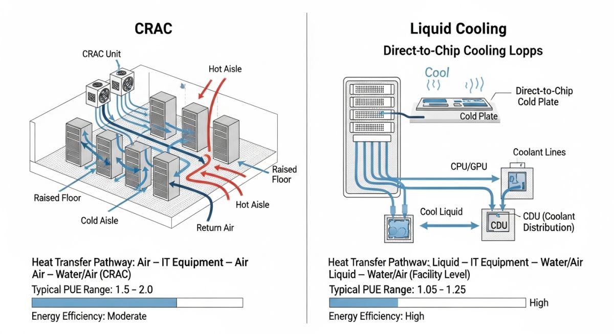
Air-Based Cooling Architectures
Computer Room Air Conditioning (CRAC) and Computer Room Air Handler (CRAH) units remain the backbone of most legacy facilities. CRAC units typically operate on a direct expansion (DX) cycle, utilizing a refrigerant loop to absorb heat. Conversely, CRAH units rely on chilled water supplied by a central plant. The critical design parameter here is the airflow volume, measured in CFM (Cubic Feet per Minute), which must be sufficient to prevent hot spots.
Field Warning: Airflow Bypass and Recirculation
In many facilities, I have seen significant energy waste due to air bypass, where cold supply air returns to the cooling unit without passing through the server racks. Implementing hot/cold aisle containment is not optional; it is a fundamental requirement to maintain the pressure differentials necessary for efficient cooling distribution.
Chilled Water System Integration
For large-scale data centres, chilled water systems offer superior scalability. The system consists of chillers, cooling towers, and a distribution network of pumps and piping. The design must account for the ASME B31.3 piping code for pressure integrity. We often employ a primary-secondary pumping arrangement to decouple the chiller flow from the load-side flow, ensuring that the chillers operate within their optimal efficiency range regardless of the instantaneous server load.
When designing these loops, we must consider the thermal inertia of the water volume. A larger volume of water in the loop provides a buffer against sudden load spikes, which is critical for maintaining stable inlet temperatures during a chiller transition or power event. Always ensure that the piping material is compatible with the water treatment chemicals used to prevent corrosion and biological growth, which can severely degrade heat transfer efficiency over time.
Cooling System Trade-offs: Selecting the appropriate thermal management architecture requires balancing operational expenditure, capital investment, and long-term reliability metrics.
Advantages
- Chilled water systems provide high heat density capacity.
- Liquid cooling significantly reduces fan power consumption.
- Modular CRAC units allow for incremental facility expansion.
- Containment strategies improve PUE by reducing air mixing.
- Advanced control systems enable real-time load matching.
Disadvantages
- DX systems suffer from lower efficiency at partial loads.
- Liquid cooling introduces potential for fluid leakage risks.
- High initial capital cost for central chiller plants.
- Complex maintenance requirements for water treatment loops.
- Air-based systems struggle with high-density rack cooling.
Cooling System Deployment: These technologies are applied across diverse sectors to ensure the continuous operation of high-performance computing and critical data infrastructure.
Hyperscale Cloud Infrastructure
Hyperscale facilities utilize massive chilled water loops with free-cooling economizers to maximize efficiency. These systems are designed for 24/7 operation with N+2 redundancy to ensure that no single component failure impacts the cooling capacity of the entire server hall.
High-Performance Computing (HPC) Labs
HPC environments often require direct-to-chip liquid cooling to manage the extreme heat flux of GPU-heavy clusters. By circulating dielectric fluid or water directly to the processor cold plate, these systems achieve thermal densities that air-based cooling simply cannot support.
Edge Computing Micro-Data Centres
Edge deployments rely on self-contained, ruggedized DX cooling units that operate independently of central plant infrastructure. These systems are optimized for small footprints and high reliability in non-traditional environments like telecommunications hubs or industrial manufacturing floors.
Selecting the appropriate thermal management architecture requires a granular understanding of how different systems handle heat density. In my experience, the choice between air-based and liquid-based cooling is dictated primarily by the rack power density, measured in kilowatts per rack, and the required Power Usage Effectiveness (PUE) targets set by the facility operators.
The following table outlines the operational thresholds and typical efficiency ranges for common cooling technologies. Note that while traditional CRAC units remain the industry standard for legacy facilities, high-density compute environments are increasingly shifting toward rear-door heat exchangers and direct-to-chip liquid cooling to maintain thermal stability without excessive fan energy consumption.
| Cooling Technology | Max Density (kW/Rack) | Efficiency (PUE Impact) | Primary Standard |
|---|---|---|---|
| CRAC/CRAH Air Cooling | 10 – 15 | Moderate (1.5 – 1.8) | ASHRAE TC 9.9 |
| In-Row Cooling | 20 – 30 | High (1.3 – 1.5) | ISO 14644 |
| Rear Door Heat Exchanger | 30 – 50 | Very High (1.2 – 1.3) | ASHRAE TC 9.9 |
| Direct-to-Chip Liquid | 100+ | Excellent (< 1.15) | ASME B31.3 |
Engineers must verify that the chosen system aligns with the facility’s existing chilled water loop capacity or if a dedicated refrigerant circuit is required. Always cross-reference these values with the specific server manufacturer’s thermal envelope requirements to avoid localized hotspots.
Effective thermal management relies on the precise integration of mechanical, electrical, and control systems. This matrix maps the critical entities involved in Data Centre Cooling Systems, providing a clear reference for the standards and physical parameters that govern their design and operational lifecycle.
By standardizing these components, we ensure that the cooling infrastructure remains resilient against fluctuating server loads. Whether dealing with fluid dynamics in a chilled water loop or airflow patterns in a raised-floor plenum, these entities represent the core building blocks of a high-availability facility.
| Entity | Acronym | Standard Reference |
|---|---|---|
| Computer Room Air Conditioner | CRAC | ASHRAE 127 |
| Power Usage Effectiveness | PUE | ISO/IEC 30134-2 |
| Chilled Water Distribution | CHW | ASME B31.1 |
| Direct Expansion | DX | AHRI 1360 |
These mappings are essential for procurement and site verification. When reviewing project specifications, ensure that all equipment submittals explicitly state compliance with these referenced standards to maintain the integrity of the cooling design.
Before commissioning any cooling infrastructure, a rigorous site verification process is mandatory. In my two decades of experience, I have found that most thermal failures stem from poor airflow management or misaligned setpoints rather than equipment failure. This checklist serves as a baseline for ensuring your Data Centre Cooling Systems are optimized for peak performance and reliability.
-
Airflow Path Integrity: Verify that all blanking panels are installed in empty rack spaces to prevent hot air recirculation, as per ASHRAE TC 9.9 guidelines. -
Chilled Water Balancing: Confirm that the differential pressure across the cooling coils matches the design specifications defined in ASME B31.3 piping codes. -
Sensor Calibration: Validate that all temperature and humidity sensors are calibrated within the tolerance levels specified by the manufacturer and the facility’s BMS requirements. -
Redundancy Testing: Perform a failover test on the N+1 or 2N cooling units to ensure that the secondary systems engage within the required time window without causing thermal spikes. -
Fluid Leak Detection: Inspect all liquid cooling connections for signs of moisture or corrosion, ensuring that leak detection systems are active and integrated into the central alarm panel.
Regular audits using this checklist will significantly reduce the risk of unplanned downtime. Always document the results of these checks in the facility’s maintenance log to maintain compliance with operational standards and insurance requirements.
Problem: Thermal Instability in High-Density Server Rows
A major financial data centre experienced recurring server shutdowns due to localized hotspots in rows exceeding 20kW per rack.
- Inadequate cold aisle containment leading to air mixing.
- Insufficient static pressure in the raised floor plenum.
- Misalignment of CRAC unit setpoints relative to actual server intake temperatures.
- High-density compute nodes exceeding the design capacity of the legacy air-cooling system.
Outcome: Successful Thermal Optimization
The implementation of a hybrid cooling strategy resolved the thermal issues and improved overall facility efficiency.
- Reduced PUE from 1.85 to 1.42 through the installation of in-row cooling units.
- Eliminated hotspots by implementing rigid aisle containment systems.
- Achieved a 30% reduction in fan energy consumption by optimizing airflow paths.
- Improved server uptime by 99.999% through better thermal management.
My recommendation for similar scenarios is to prioritize airflow containment before investing in additional cooling capacity. Often, the existing infrastructure is sufficient if the air distribution is properly managed and the thermal bypass is eliminated.
What is the primary difference between CRAC and CRAH units?
The distinction lies in the cooling medium and the refrigeration cycle. CRAC (Computer Room Air Conditioner) units utilize a self-contained refrigerant cycle, similar to a standard air conditioner, making them ideal for smaller rooms or facilities without a central chilled water plant.
- CRAH (Computer Room Air Handler) units rely on chilled water supplied by a central plant, utilizing a heat exchanger to cool the air.
- CRAH units are generally more efficient for large-scale data centres due to the economies of scale provided by central chillers.
- Both systems must comply with ASHRAE 127 standards for performance testing and rating.
How does aisle containment improve cooling efficiency?
Aisle containment prevents the mixing of hot exhaust air with cold supply air, which is the leading cause of thermal inefficiency in data centres. By physically separating these streams, the cooling units can operate at higher supply temperatures, which significantly improves the efficiency of the refrigeration cycle.
- Cold aisle containment keeps the supply air directed solely at the server intakes.
- Hot aisle containment captures exhaust air and returns it directly to the cooling units.
- This separation allows for higher return air temperatures, increasing the cooling capacity of the existing equipment.
What are the benefits of liquid cooling for high-density racks?
Liquid cooling is significantly more effective at heat transfer than air, as water has a much higher thermal conductivity and heat capacity. This allows for the cooling of extremely high-density racks that would be impossible to manage with traditional air-based systems.
- Direct-to-chip cooling removes heat directly from the processor, reducing the need for high-velocity fans.
- Immersion cooling submerges the entire server in a dielectric fluid, providing uniform thermal management.
- Liquid cooling systems enable higher rack densities, reducing the physical footprint of the data centre.
Why is PUE a critical metric for cooling design?
Power Usage Effectiveness (PUE) is the industry-standard metric for measuring the energy efficiency of a data centre. It is calculated as the ratio of total facility power to the power delivered to the IT equipment, with cooling systems often being the largest contributor to the non-IT power load.
- A lower PUE indicates that a higher percentage of energy is being used for actual computing rather than overhead.
- Optimizing cooling systems is the most effective way to lower the PUE of an existing facility.
- PUE targets are often mandated by sustainability regulations and corporate ESG goals.
How do I ensure compliance with ASHRAE TC 9.9?
Compliance with ASHRAE TC 9.9 requires adhering to the recommended thermal envelopes for server intake temperatures and humidity levels. This involves regular monitoring and the use of appropriate cooling control strategies to maintain these conditions under varying IT loads.
- Design the cooling system to operate within the allowable temperature ranges defined by the standard.
- Implement robust monitoring systems to track intake temperatures at the top, middle, and bottom of every rack.
- Regularly review the facility’s thermal performance against the latest ASHRAE guidelines to ensure ongoing compliance.
What are the risks of improper humidity control?
Improper humidity control can lead to significant hardware failures. Low humidity increases the risk of electrostatic discharge (ESD), which can damage sensitive electronic components, while high humidity can lead to condensation and corrosion on circuit boards.
- Maintain humidity levels within the recommended range to prevent both ESD and corrosion.
- Use humidification and dehumidification systems integrated into the CRAC/CRAH units.
- Monitor humidity levels continuously to ensure they remain within the safe operating envelope for IT equipment.
Complete Course on
Piping Engineering
Check Now
Key Features
- 125+ Hours Content
- 500+ Recorded Lectures
- 20+ Years Exp.
- Lifetime Access
Coverage
- Codes & Standards
- Layouts & Design
- Material Eng.
- Stress Analysis

📚 Recommended Resources: Data Centre Cooling Systems
Read these Guides
- 📄 Backup Generators for Data Centres: Engineering Design and Reliability
- 📄 Uninterruptible Power Supply Systems: Engineering Design and Reliability Guide
- 📄 Power Systems in Data Centres: Engineering Reliability and Design Standards
- 📄 Edge Data Centres Explained: Infrastructure Design and Deployment Strategies