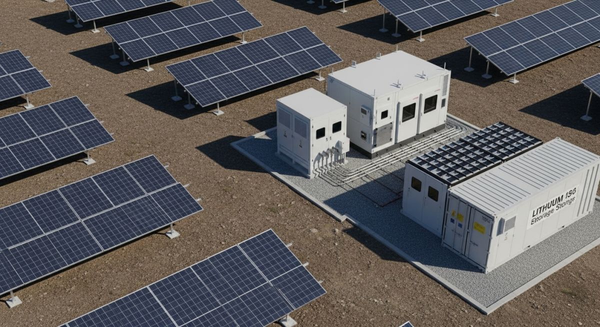
BESS Integration with Solar Power Plants: Engineering for Grid Stability
In my two decades of experience managing large-scale energy infrastructure, I have observed that the primary bottleneck for solar expansion is no longer the PV module efficiency, but the grid’s inability to absorb volatile, non-dispatchable power. BESS integration with solar power plants transforms a passive generation asset into a dynamic, dispatchable power station capable of responding to real-time frequency fluctuations.
When we design these systems, we are not just adding batteries; we are engineering a complex power conversion interface that must balance DC-coupled or AC-coupled architectures against site-specific thermal and electrical constraints. This guide explores the technical rigor required to move beyond simple peak shaving into advanced grid-forming control strategies.
Key Takeaways
- Mitigation of solar curtailment through intelligent charge-discharge scheduling.
- Comparison of DC-coupled versus AC-coupled system topologies for efficiency.
- Implementation of frequency response and voltage regulation via BESS.
- Economic optimization through energy arbitrage and capacity market participation.
Technical Design for BESS Integration with Solar Power Plants
BESS Integration with Solar Power Plants: The systematic application of lithium-ion or flow battery technologies to decouple solar generation from load demand, requiring precise control of power conversion systems and thermal management protocols.
Designing a BESS-integrated solar facility requires a deep dive into the power conversion chain. The choice between AC-coupling and DC-coupling is the most critical decision in the early design phase. In AC-coupled systems, the BESS and the PV array operate as independent entities, each with its own inverter, connected at the medium-voltage collection bus. This provides modularity but introduces double conversion losses, typically ranging from 3% to 5% per conversion stage.
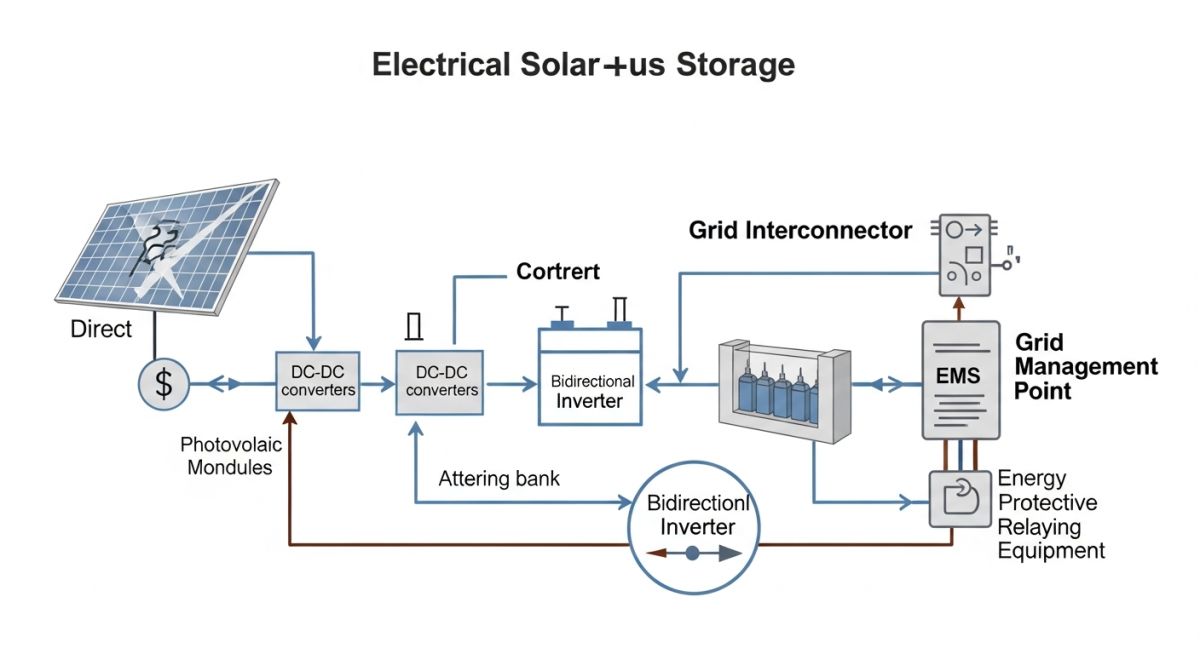
Conversely, DC-coupled systems utilize a shared inverter, where the PV array and the BESS connect to a common DC bus via a DC-DC converter. This architecture significantly reduces conversion losses by eliminating the need for a second inverter stage. However, it complicates the protection coordination, as the DC bus must handle both the PV current and the high-discharge current from the battery bank during fault conditions.
Field Warning: Protection Coordination
When integrating BESS, the fault current contribution from the battery inverter can be significantly higher than that of a standard PV inverter. Ensure that your circuit breakers and protective relays are rated for the combined fault current contribution of both the PV array and the BESS, adhering to NFPA 70 (NEC) requirements for energy storage systems.
From a calculation standpoint, the sizing of the BESS is governed by the required duration of discharge and the depth of discharge (DoD) limits. If a plant requires 50 MW of peak shaving for 4 hours, the energy capacity (E) is calculated as E = P * t / (n * DoD), where P is power, t is time, and n is the round-trip efficiency. For a 90% efficient system with an 80% DoD, the required nameplate capacity would be 50 * 4 / (0.9 * 0.8) = 277.7 MWh.
Thermal management is equally critical. Battery cells must operate within a narrow temperature window, typically 15 to 35 degrees Celsius, to prevent accelerated degradation. I recommend liquid cooling systems for large-scale installations, as they provide superior heat transfer coefficients compared to forced-air cooling, especially in high-ambient-temperature environments common to solar-rich regions.
BESS Operational Trade-offs: A technical evaluation of the performance gains versus the capital and maintenance complexities inherent in hybrid renewable energy storage systems.
Advantages
- Curtailment Mitigation: Captures excess energy that would otherwise be clipped by inverter limits.
- Ancillary Services: Enables participation in frequency regulation and spinning reserve markets.
- Ramp Rate Control: Smooths out intermittent solar output to meet strict grid interconnection requirements.
- Energy Arbitrage: Allows shifting of solar generation to high-demand, high-price evening periods.
Disadvantages
- High CAPEX: Significant upfront investment in battery modules and power conversion hardware.
- Degradation Management: Complex state-of-health (SoH) monitoring required to manage cycle life.
- Fire Safety Risks: Increased complexity in thermal runaway mitigation and suppression systems.
- Regulatory Hurdles: Stringent permitting and grid-code compliance for hybrid plant configurations.
Industrial Energy Optimization: Strategic deployment of BESS in utility-scale and commercial environments to maximize asset utilization and grid reliability.
Utility-Scale Peak Shaving
Large-scale solar plants utilize BESS to flatten the generation curve during peak afternoon hours. By discharging stored energy during the evening ramp, the plant maintains a consistent power output, preventing grid congestion and avoiding utility-imposed penalties for non-dispatchable generation.
Microgrid Frequency Regulation
In remote or islanded microgrids, BESS provides the necessary inertia to stabilize frequency. The battery system acts as a fast-acting buffer, absorbing sudden drops in solar irradiance and preventing frequency excursions that could trigger load shedding or system instability.
Commercial Demand Charge Reduction
Commercial facilities with rooftop solar arrays deploy BESS to mitigate high demand charges. By monitoring real-time facility load, the BESS discharges during peak consumption intervals, effectively clipping the facility’s peak demand and significantly reducing monthly utility billing costs.
When evaluating BESS integration with solar power plants, engineers must prioritize specific performance metrics that dictate the system’s ability to handle rapid ramp rates and diurnal energy shifting. The following table outlines the critical technical parameters I consistently monitor during the front-end engineering design (FEED) phase to ensure compliance with IEEE 1547 standards for distributed energy resources.
These values represent the operational boundaries for lithium-ion battery chemistries commonly deployed in utility-scale solar-plus-storage projects. Understanding these thresholds is vital for sizing the power conversion system (PCS) and ensuring the battery management system (BMS) can effectively communicate with the plant controller to mitigate solar intermittency.
| Parameter | Typical Range | Engineering Impact |
|---|---|---|
| C-Rate (Discharge) | 0.5C to 2.0C | Determines peak power output capability |
| Round Trip Efficiency | 85% to 92% | Directly affects project IRR and LCOE |
| Cycle Life (80% DoD) | 4,000 to 8,000 | Dictates long-term asset replacement schedule |
| Response Time | Less than 100ms | Critical for frequency regulation compliance |
By maintaining these parameters within the specified design envelopes, operators can maximize the lifespan of the BESS while ensuring the solar plant remains a reliable, dispatchable asset for the grid operator.
The integration of BESS into solar infrastructure requires a sophisticated mapping of electrical, mechanical, and software entities. As a lead engineer, I utilize this matrix to ensure that every component—from the DC-coupled solar array to the grid-interconnection point—is properly accounted for in the NFPA 855 fire safety and electrical design documentation.
This matrix serves as a cross-reference tool for project stakeholders, ensuring that the physical hardware specifications align with the software control logic required for advanced grid services like synthetic inertia and voltage support. Proper alignment here prevents costly field retrofits and ensures the plant meets all regional grid code requirements.
| Entity | Acronym | Standard Reference |
|---|---|---|
| Battery Management System | BMS | UL 1973 |
| Power Conversion System | PCS | UL 1741 |
| Energy Management System | EMS | IEC 61850 |
| State of Charge | SoC | IEEE 2030.2 |
This structured approach allows for seamless integration between the solar PV inverters and the battery storage inverters, creating a unified plant control architecture that is both resilient and highly efficient.
Before commissioning any BESS integration with solar power plants, I conduct a rigorous site verification process. This ensures that the physical installation meets the design intent and safety requirements outlined in the National Electrical Code (NEC) Article 706. Failure to verify these points can lead to significant delays during the grid interconnection testing phase.
-
01.
Verify clearance distances around battery enclosures to meet fire suppression and ventilation requirements per NFPA 855. -
02.
Confirm the grounding grid continuity between the solar array and the BESS container to prevent potential differences during fault conditions. -
03.
Validate the communication latency between the plant controller and the PCS to ensure sub-100ms response times for frequency regulation. -
04.
Inspect the thermal management system (HVAC or liquid cooling) for proper setpoints and alarm integration with the central SCADA system. -
05.
Check the state of charge (SoC) balancing across parallel battery strings to prevent premature degradation of individual modules.
Each of these checkpoints is non-negotiable. In my experience, the most common point of failure is the communication link between the solar inverter and the BESS controller. Always perform a loop-check of the Modbus or DNP3 signals before energizing the system. Documenting these checks provides the necessary audit trail for utility interconnection agreements and insurance compliance.
The Challenge: Solar Curtailment and Voltage Instability
A 50MW solar plant in a remote region faced severe curtailment due to grid congestion and voltage fluctuations during peak solar irradiance hours.
- Grid operator imposed a 30% curtailment limit during midday.
- Voltage spikes at the point of interconnection (POI) exceeded utility limits.
- Lack of reactive power support led to frequent inverter tripping.
The Outcome: Successful BESS Integration
By integrating a 20MW/40MWh BESS, the plant successfully mitigated curtailment and stabilized the local grid voltage.
- Curtailment reduced from 30% to less than 5% annually.
- Voltage regulation improved through dynamic reactive power injection.
- Increased revenue through participation in frequency response markets.
My recommendation for similar projects is to conduct a thorough power flow study before finalizing the BESS capacity. Often, a smaller storage system can provide the necessary reactive power support to solve voltage issues, even if the primary goal is energy shifting. Always prioritize the grid operator’s specific requirements for ancillary services to maximize the project’s economic viability.
What is the primary difference between DC and AC coupling?
- DC coupling is ideal for new greenfield projects where equipment can be optimized together.
- AC coupling connects the BESS to the AC side, making it easier to retrofit existing solar plants.
- AC coupling allows the BESS and solar to operate independently, providing greater system redundancy.
How does BESS help with solar curtailment?
- The energy is stored during peak production hours and discharged during evening peak demand.
- This process effectively shifts the solar generation profile to match the load curve.
- It prevents the loss of revenue associated with forced curtailment by the grid operator.
What standards govern BESS safety?
- UL 1973 covers the safety of batteries for use in stationary applications.
- NFPA 855 provides comprehensive requirements for the installation of stationary energy storage systems.
- UL 9540 addresses the safety of the entire energy storage system, including the PCS and BMS.
How is peak shaving achieved with BESS?
- The EMS monitors the site load and triggers the BESS discharge when demand exceeds a pre-set threshold.
- This reduces demand charges for the facility, significantly improving the project’s economic return.
- It also helps stabilize the local distribution network by reducing stress on transformers.
What is the role of the EMS in BESS?
- It optimizes the dispatch of solar and battery power based on market prices and grid signals.
- The EMS ensures that the BESS operates within its safe state-of-charge and temperature limits.
- It provides the necessary data logging and reporting for regulatory compliance and performance monitoring.
Can BESS provide synthetic inertia?
- This is achieved through fast-acting control algorithms that adjust power output in response to grid frequency deviations.
- It is increasingly required by grid operators as the penetration of inverter-based resources increases.
- Synthetic inertia helps maintain grid stability during sudden load changes or generation losses.
Complete Course on
Piping Engineering
Check Now
Key Features
- 125+ Hours Content
- 500+ Recorded Lectures
- 20+ Years Exp.
- Lifetime Access
Coverage
- Codes & Standards
- Layouts & Design
- Material Eng.
- Stress Analysis

📚 Recommended Resources: BESS Integration with Solar Power Plants
Read these Guides
- 📄 Engineering Utility-Scale BESS Plant Design: A Comprehensive Technical Guide
- 📄 Power Conversion System Design: Essential Guide for Modern Grid Integration
- 📄 Major Components of a BESS Plant: A Technical Engineering Overview
- 📄 Lithium-Ion Batteries Explained for BESS Applications: A Technical Guide