Wind Farm Electrical System Design: A Technical Overview
In my two decades of experience managing utility-scale energy projects, I have found that the electrical architecture of a wind farm is far more than just connecting turbines to a grid. It is a complex balancing act of reactive power compensation, voltage regulation, and thermal management of underground cable networks. Every design decision, from the choice of collector voltage to the selection of grounding transformers, directly impacts the project’s Levelized Cost of Energy (LCOE).
This guide explores the critical components of wind farm electrical system design, focusing on the transition from low-voltage turbine outputs to high-voltage transmission. We will examine the technical nuances of collector systems, the importance of grid code compliance, and the engineering rigor required to minimize transmission losses across vast project sites.
Key Takeaways for Engineers:
- Optimizing collector voltage levels to reduce copper losses.
- Understanding the impact of harmonic distortion on power quality.
- Navigating grid code requirements for fault ride-through capabilities.
- Implementing robust protection schemes for radial and ring-main collector topologies.
Core Technical Analysis: Wind Farm Electrical System Design
Wind Farm Electrical System Design: The engineering process of sizing and configuring electrical components to facilitate efficient power evacuation from wind turbine generators to the point of interconnection while maintaining strict adherence to thermal and voltage stability limits.
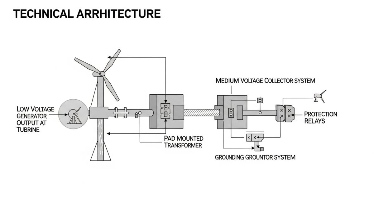
The design begins at the turbine transformer, typically a pad-mounted unit stepping up voltage from the generator level (often 690V) to the collector voltage (typically 33kV or 34.5kV). The primary challenge here is the calculation of the collector system impedance. We must account for the resistance and reactance of the underground cable network, which often spans several kilometers. Using the IEC 60287 standard for cable rating, we calculate the ampacity based on soil thermal resistivity, burial depth, and grouping factors.
Field Warning: Thermal Runaway Risks
In my experience, the most common failure point in collector systems is improper cable trench design. When cables are bunched together without adequate thermal backfill, the localized heating leads to insulation degradation. Always verify the soil thermal resistivity (Rho) at the site before finalizing cable cross-sections.
Voltage drop calculations are performed using the standard formula: Delta V = I * (R * cos(phi) + X * sin(phi)), where R and X are the resistance and reactance of the cable per unit length. For a typical 34.5kV collector circuit, we aim to keep the total voltage drop below 3% to 5% under full load conditions. If the drop exceeds these limits, we must either increase the conductor size or install shunt capacitor banks at the substation.
Protection systems are equally critical. We utilize directional overcurrent relays and differential protection for the main power transformers. The coordination study must ensure that a fault at a single turbine does not trip the entire collector string. We follow IEEE 1547 for distributed resource interconnection, ensuring that the protection settings allow for fault ride-through (FRT) during transient grid disturbances.
Finally, the substation acts as the heart of the system. It houses the main step-up transformer (GSU), which elevates the collector voltage to the transmission voltage (e.g., 115kV, 230kV, or 500kV). The GSU must be specified with an appropriate impedance (typically 8-12%) to limit fault currents while maintaining voltage regulation. We also integrate STATCOM or SVC units if the grid operator requires dynamic reactive power support to maintain the power factor at the point of common coupling.
System Architecture Trade-offs: The evaluation of electrical design topologies based on reliability, cost-efficiency, and operational flexibility within utility-scale renewable energy environments.
Advantages
- Radial collector systems minimize initial capital expenditure (CAPEX) for smaller wind farms.
- Ring-main topologies provide N-1 redundancy, allowing continued operation during cable faults.
- Modern digital protection relays allow for remote monitoring and predictive maintenance.
- High-voltage transmission reduces I-squared-R losses over long distances.
Disadvantages
- Underground cable networks are susceptible to damage during site excavation.
- High harmonic content from power electronics requires expensive filtering solutions.
- Complex grid compliance testing increases project commissioning timelines.
- Transformer oil leakage poses environmental risks requiring secondary containment systems.
Industry Deployment Scenarios: The practical implementation of electrical design standards across diverse utility-scale and industrial power generation environments.
Utility-Scale Onshore Wind Farms
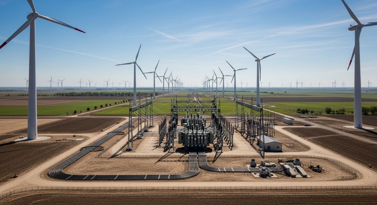
These projects utilize standard 34.5kV collector systems to aggregate power from 50 to 100+ turbines. The design focuses on minimizing cable trenching costs while ensuring the substation can handle the aggregate capacity of the entire farm under peak wind conditions.
Offshore Wind Power Evacuation
Offshore applications require high-voltage direct current (HVDC) or high-voltage alternating current (HVAC) subsea cables. The electrical design must account for extreme environmental conditions, including salt spray corrosion and subsea pressure, necessitating specialized armored cabling and offshore platform substations.
Industrial Microgrid Integration
Large industrial facilities often integrate wind energy directly into their internal distribution networks. This requires sophisticated power management systems to balance the intermittent nature of wind generation with the facility’s base load, often utilizing battery energy storage systems (BESS) for frequency regulation.
In my two decades of experience, the selection of electrical components for utility-scale wind farms is governed by strict adherence to IEEE and IEC standards. The following table outlines the typical voltage levels and insulation coordination requirements I encounter during the front-end engineering design (FEED) phase of large-scale renewable projects. These parameters are critical for ensuring the longevity of the collector system and minimizing downtime caused by insulation failure or harmonic resonance.
Engineers must carefully evaluate the Basic Insulation Level (BIL) against the site-specific lightning density and switching surge profiles. Failure to align these ratings with the ASME-compliant structural supports or the environmental conditions of the wind farm can lead to catastrophic equipment failure. Always verify that the selected switchgear and transformer ratings account for the derating factors associated with high-altitude installations or extreme ambient temperature fluctuations common in remote wind energy sites.
| Component | Typical Voltage | Standard Reference | Key Design Factor |
|---|---|---|---|
| Collector Cable | 34.5 kV | ICEA S-94-649 | Ampacity & Charging Current |
| Pad-Mount Transformer | 34.5/0.69 kV | IEEE C57.12.34 | Temperature Rise Limits |
| GIS Switchgear | 145 kV | IEC 62271-203 | SF6 Gas Pressure Monitoring |
The complexity of modern wind farm electrical system design requires a rigorous mapping of physical assets to their respective regulatory and performance frameworks. This matrix serves as a high-level reference for project managers and lead electrical engineers to ensure that every node in the collector system—from the turbine generator to the point of interconnection (POI)—is documented and compliant with regional grid codes.
By categorizing these entities, we can better manage the interface between the wind turbine generator (WTG) and the balance of plant (BOP) infrastructure. I have found that maintaining this level of granular detail is the most effective way to prevent scope creep and ensure that the protection relay settings are coordinated correctly across the entire collector string. This matrix should be updated throughout the project lifecycle as site conditions or grid requirements evolve.
| Entity | Acronym | Primary Function | Standard |
|---|---|---|---|
| Wind Turbine Generator | WTG | Power Conversion | IEC 61400 |
| Point of Interconnection | POI | Grid Integration | IEEE 1547 |
| Supervisory Control | SCADA | System Monitoring | IEC 61850 |
Effective site verification is the cornerstone of a successful commissioning phase. In my experience, skipping these fundamental checks often leads to latent defects that only manifest during high-wind events or grid disturbances. This checklist is designed to ensure that the physical installation matches the design intent and complies with all safety and performance standards.
-
Grounding Continuity: Verify that all turbine foundations and substation structures are bonded to the main grounding grid per IEEE 80 standards. -
Cable Termination Integrity: Inspect all medium-voltage cable terminations for proper stress cone installation and torque settings to prevent partial discharge. -
Relay Logic Verification: Perform secondary injection testing on all protection relays to confirm trip times align with the NERC grid compliance requirements. -
Transformer Oil Analysis: Conduct dissolved gas analysis (DGA) on all pad-mount and substation transformers to establish a baseline before energization. -
SCADA Communication Check: Validate that all telemetry signals from the turbines are correctly mapped to the central control room for real-time monitoring.
Always document these findings in a formal commissioning report. If any value falls outside the specified tolerance, do not proceed to energization until a root cause analysis is performed and corrective actions are verified by the lead engineer.
The Problem: Recurring Cable Faults
During a recent 200MW wind farm project, we experienced repeated cable failures in the collector system during the first six months of operation.
- Improper cable bending radius during installation in cold weather.
- Inadequate moisture sealing at the turbine base entry points.
- High levels of partial discharge detected in the cable splices.
- Lack of proper tension relief on vertical cable runs.
The Outcome: System Reliability Restored
By implementing a comprehensive remediation plan, we successfully stabilized the collector system and eliminated the fault occurrences.
- Replaced all compromised cable segments with cold-shrink terminations.
- Implemented a strict pre-installation cable heating protocol.
- Installed additional mechanical supports to reduce cable strain.
- Achieved 99.9% uptime for the collector system post-remediation.
My recommendation for future projects is to prioritize the training of installation crews on medium-voltage cable handling. The cost of proper training is negligible compared to the expense of trenching and replacing faulty underground cables after the site has been fully landscaped.
Frequently Asked Engineering Questions
How do I determine the optimal collector voltage?
- Evaluate the total length of the collector strings to minimize voltage drop.
- Consider the cost of switchgear and transformer insulation at higher voltage levels.
- Analyze the charging current limits of the underground cables.
- Ensure compatibility with existing regional grid infrastructure and utility requirements.
What are the primary grid compliance requirements?
- Fault Ride-Through (FRT) capabilities to maintain stability during grid disturbances.
- Reactive power control to support voltage regulation at the point of interconnection.
- Harmonic distortion limits as defined by IEEE 519.
- Active power curtailment and frequency response requirements.
How do I manage harmonic resonance in collector systems?
- Perform detailed harmonic impedance studies during the design phase.
- Use passive or active filtering if resonance frequencies align with turbine switching frequencies.
- Coordinate with turbine manufacturers to adjust control parameters if necessary.
- Ensure that the transformer design accounts for potential harmonic heating effects.
What is the role of SCADA in wind farm design?
- Monitoring power output and availability for grid reporting.
- Managing protection relay status and fault event logging.
- Enabling remote control of circuit breakers and transformer tap changers.
- Facilitating predictive maintenance through data analytics and trend monitoring.
How do I select the right transformer for the turbine?
- Ensure the kVA rating matches the turbine’s peak output plus a safety margin.
- Specify low-loss designs to improve overall farm energy yield.
- Verify that the transformer can withstand the mechanical stresses of short-circuit events.
- Choose appropriate cooling methods based on the turbine enclosure design and ambient conditions.
What are the best practices for grounding?
- Perform soil resistivity testing early in the site development phase.
- Design the grid to meet the safety limits defined in IEEE 80.
- Ensure all metallic structures are bonded to the grid using corrosion-resistant materials.
- Regularly inspect and test the grounding system to ensure its integrity over the life of the project.
Complete Course on
Piping Engineering
Check Now
Key Features
- 125+ Hours Content
- 500+ Recorded Lectures
- 20+ Years Exp.
- Lifetime Access
Coverage
- Codes & Standards
- Layouts & Design
- Material Eng.
- Stress Analysis

📚 Recommended Resources: Wind Farm Electrical System Design
Read these Guides
- 📄 Offshore Wind Farm Engineering: Design, Foundations, and Electrical Systems
- 📄 Wind Farm Layout and Micro-Siting: Optimizing Turbine Placement for Yield
- 📄 Wind Turbine Generators Explained: Engineering Design and Selection Criteria
- 📄 Wind Resource Assessment for Wind Power Projects: A Technical Guide
Related posts:
![Senior engineer analyzing a comprehensive Geotechnical Investigation Report and structural drawings on a construction site office desk.]()
How to Read and Interpret Geotechnical Investigation Reports for Engineers
![Detailed industrial site topographical survey drawing showing contour lines, spot levels, and utility mapping for piping design.]()
Mastering Topographical Survey Reports for Precision Piping Engineering Design
![Geotechnical engineer operating a soil drilling rig for site investigation and core sampling on a construction project.]()
Essential Geotechnical Investigation Terminology for Structural Foundation Design Success
![Professional land surveyor using a total station on an industrial construction site for topographical surveys.]()
Topographical Surveys: Essential Terminology for Piping and Civil Engineering
![A professional geotechnical drilling rig operating on a construction site with various soil sampling and testing instruments laid out for inspection.]()
Essential Survey Instruments Used in Geotechnical Investigations for Site Analysis
![A robotic total station mounted on a tripod at a construction site for topographical surveying.]()
Topographical Survey Instruments: A Guide to Modern Field Equipment