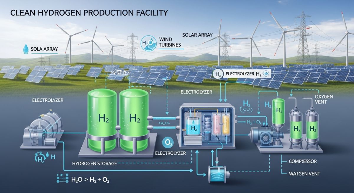
Green Hydrogen Production Process and Industrial Plant Design Guide
In my 20 plus years of piping and process engineering experience, I have watched the industrial landscape shift from heavy fossil-fuel reliance to clean, sustainable alternatives. Today, designing systems for green hydrogen production is no longer a niche pilot project; it is a core requirement for modern industrial plants. When we design these facilities, we are not just dealing with standard gas piping. We are managing high-pressure, highly diffusive molecules that demand rigorous adherence to safety codes, precise material selection, and deep electrochemical understanding. This guide shares my hands-on field experience in designing, sizing, and commissioning safe, high-efficiency water electrolysis plants.
Key Takeaways for Plant Engineers
- Understand the thermodynamic and electrochemical principles of water electrolysis under ISO 22734 standards.
- Master the differences between Alkaline, PEM, and Solid Oxide electrolyzers for proper plant integration.
- Apply ASME B31.12 design factors to mitigate hydrogen embrittlement in high-pressure piping.
- Implement robust safety barriers, ventilation, and leak detection systems in compliance with NFPA 2.
How Does Green Hydrogen Production Work Safely?
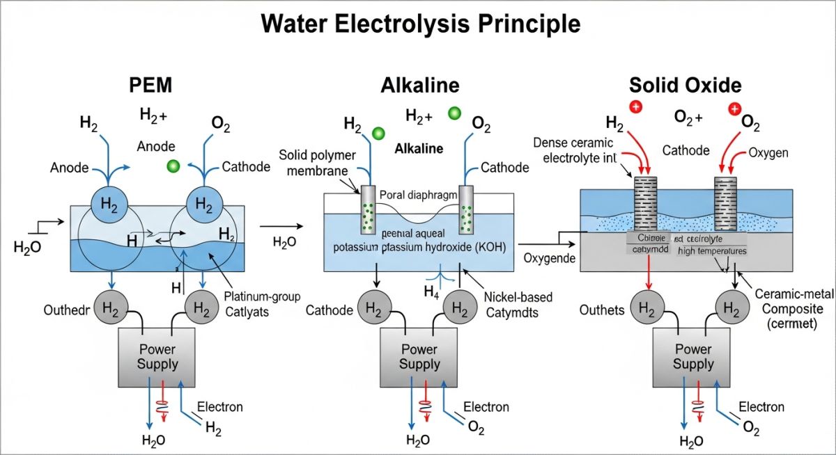
At the heart of green hydrogen production is the water electrolysis process. By passing a direct electrical current (DC) through water in the presence of an electrolyte, we force the water molecules to split. The reduction reaction occurs at the cathode to produce hydrogen, while the oxidation reaction occurs at the anode to produce oxygen.
The Thermodynamics of Water Electrolysis
To design an efficient system, we must look at the thermodynamics. The total energy required for water splitting is represented by the change in Enthalpy (delta H). This energy is the sum of the Gibbs Free Energy change (delta G), which must be supplied as electrical energy, and the thermal energy requirement represented by the product of temperature and entropy change (T * delta S):
At standard temperature (298.15 K) and pressure (1 bar), the minimum voltage required to initiate water splitting is the thermoneutral voltage, which is approximately 1.48 Volts per cell. The reversible cell voltage, where no heat is generated or absorbed, is 1.23 Volts. In real-world industrial operations, we operate above the thermoneutral voltage (typically 1.6 to 2.0 Volts per cell) to overcome internal resistances, activation overpotentials, and mass transport limitations. This excess voltage is converted directly into waste heat, which our piping and cooling systems must safely dissipate.
Calculating Hydrogen Production Rates
To size downstream piping, control valves, and storage vessels, we use Faraday’s Law of Electrolysis. The theoretical mass flow rate of hydrogen produced is directly proportional to the electrical current passing through the electrolyzer stack:
Where:
– I = Stack Current in Amperes (A)
– n = Number of cells in series within the stack
– M_H2 = Molar mass of hydrogen (approximately 2.016 g/mol)
– z = Number of electrons transferred per molecule of H2 (z = 2)
– F = Faraday’s Constant (96,485 Coulombs/mol)
Comparing Electrolyzer Technologies
As a piping engineer, the choice of electrolyzer technology dictates the entire balance of plant (BOP) design. The three dominant industrial technologies are:
- Alkaline Electrolysis (AEL): Uses a liquid potassium hydroxide (KOH) electrolyte. It is a mature, cost-effective technology but operates at lower current densities and requires robust chemical handling systems to manage the corrosive liquid electrolyte.
- Proton Exchange Membrane (PEM): Utilizes a solid polymer membrane. It operates at high current densities, offers excellent dynamic response to fluctuating renewable power, and delivers high-purity hydrogen at elevated pressures (typically 30 to 50 bar), reducing downstream compression costs.
- Solid Oxide Electrolysis (SOEC): A high-temperature technology (600 to 850 degrees Celsius) utilizing a ceramic solid state electrolyte. It offers the highest thermodynamic efficiency when waste heat or steam is available from nearby industrial processes, though thermal stress on piping is a major design challenge.
| Parameter | Alkaline (AEL) | Proton Exchange (PEM) | Solid Oxide (SOEC) |
|---|---|---|---|
| Operating Temperature | 60 – 90 °C | 50 – 80 °C | 650 – 850 °C |
| Operating Pressure | Atmospheric to 30 bar | 30 to 50 bar | Atmospheric to 15 bar |
| Specific Power Consumption | 50 – 65 kWh/kg H2 | 55 – 70 kWh/kg H2 | 40 – 50 kWh/kg H2 |
| Gas Purity (Before Purifier) | > 99.5% | > 99.99% | > 99.9% |
| Dynamic Response Time | Minutes | Seconds | Hours |
| System Component | Key Acronym | Design Parameter | Applicable Standard |
|---|---|---|---|
| Electrolyzer Stack Assembly | ESA | Current Density, Cell Voltage | ISO 22734 |
| Hydrogen Piping Network | HPN | Wall Thickness, Material Grade | ASME B31.12 |
| Deoxygenation Unit | DEOXO | Catalyst Bed Temperature, O2 ppm | ASME Section VIII Div 1 |
| Pressure Swing Adsorption | PSA | Cycle Time, Dew Point (-70 °C) | ISO 14687 Grade D |
Commissioning Green Hydrogen Production Plant Facilities
Before introducing power or water into a newly constructed green hydrogen production facility, we must execute a rigorous pre-commissioning checklist. Hydrogen’s wide flammability range (4% to 75% in air) and low ignition energy mean that even minor installation errors can lead to catastrophic failures.
Field Engineering Checklist
-
Piping Material Verification: Confirm all hydrogen-contact piping is constructed from low-carbon austenitic stainless steel (e.g., 316/316L) with a minimum nickel content of 12% to prevent hydrogen embrittlement.
-
Helium Leak Testing: Perform a high-pressure leak test using a helium-nitrogen mix (minimum 10% helium) at 100% of design pressure, utilizing mass spectrometer leak detectors. Bubble testing is insufficient for hydrogen service.
-
Electrical Grounding & Bonding: Verify that all piping segments, flanges, vessels, and electrolyzer frames are electrically bonded and grounded to earth. Resistance to ground must be less than 10 Ohms to prevent static discharge.
-
Nitrogen Purge Sequence: Validate that the automated nitrogen purging sequence successfully reduces oxygen levels below 1% before hydrogen is introduced, and reduces hydrogen levels below 1% before opening systems to air.
-
Safety Relief Valve Venting: Ensure all safety relief valves (SRVs) vent to a dedicated, elevated hydrogen vent stack designed in accordance with CGA G-5.5, complete with flame arrestors and purge gas connections.
Field Case Study: Real-World Application
The Problem: Hydrogen Embrittlement and Micro-Leaks
During the commissioning of a 10 MW PEM green hydrogen production facility, the field team reported recurring pressure drops in the high-pressure product line (operating at 40 bar). A review of the piping isometric drawings revealed that the contractor had substituted standard 304L stainless steel fittings for the specified high-nickel 316L fittings in several non-welded instrument connections. Within 120 hours of operation, micro-cracking occurred due to hydrogen-induced stress cracking (HISC), resulting in hazardous micro-leaks near the compressor skid.
The Outcome: Remediation and Material Standardization
I was brought in to lead the forensic engineering investigation. We immediately shut down the affected train and isolated the piping. Using Positive Material Identification (PMI) guns, we scanned every fitting on site. We replaced all 304L components with dual-certified 316/316L stainless steel fittings containing a minimum of 13.5% nickel. We also redesigned the piping layout to reduce mechanical vibration from the reciprocating compressor, which was accelerating the fatigue cracking. Following these modifications and a successful helium leak test, the plant resumed operations with zero pressure loss and has operated safely for over two years.
Direct Recommendation: Never compromise on material specifications in hydrogen service. Implement a strict 100% PMI program for all pressure-retaining components prior to installation, regardless of material test reports (MTRs) provided by suppliers.
Frequently Asked Engineering Questions
Why is 316L stainless steel preferred over 304L for green hydrogen piping?
What are the main piping design codes for hydrogen facilities?
How does water purity affect electrolyzer performance?
What is the role of a Deoxo unit in green hydrogen production?
How do we handle thermal expansion in high-temperature SOEC systems?
What are the ventilation requirements for indoor electrolyzer installations?
===
Complete Course on
Piping Engineering
Check Now
Key Features
- 125+ Hours Content
- 500+ Recorded Lectures
- 20+ Years Exp.
- Lifetime Access
Coverage
- Codes & Standards
- Layouts & Design
- Material Eng.
- Stress Analysis

