Table of Contents
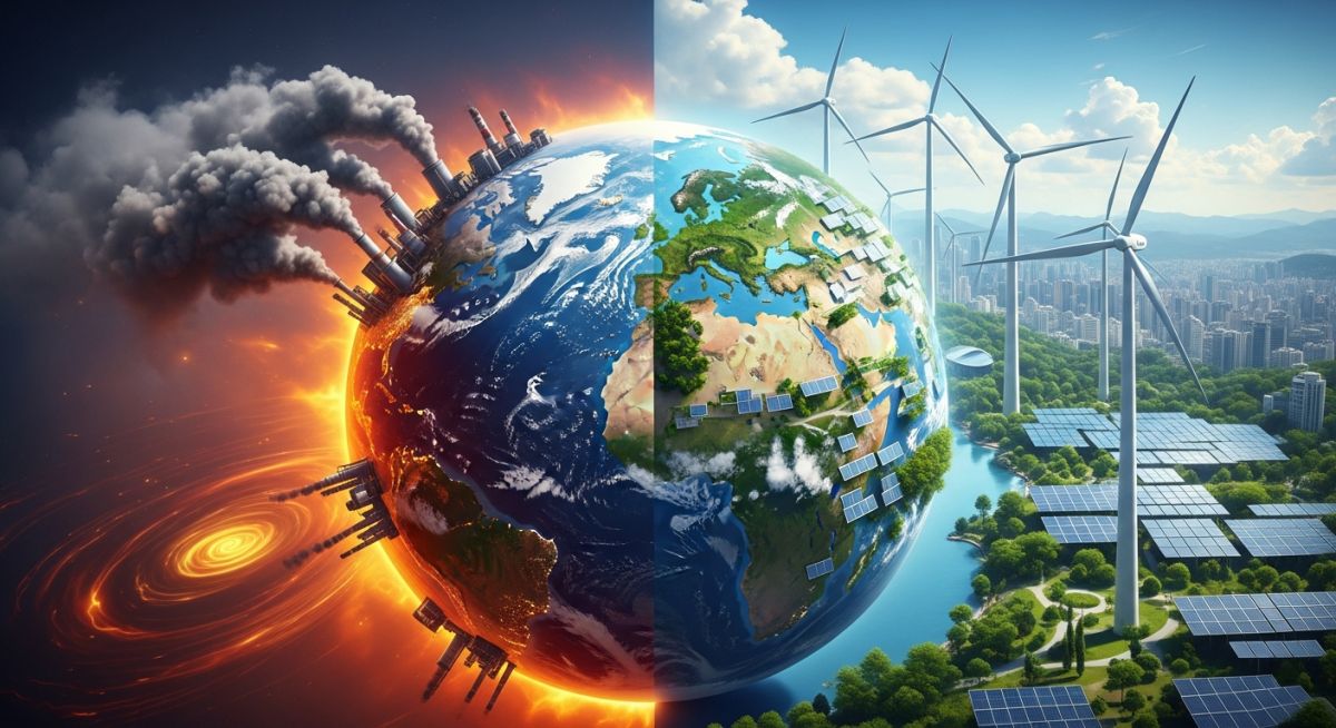
What is Greenhouse Effect and Net-Zero Carbon Emission?
In my 20-plus years of designing piping systems and process plants, I have watched our industry undergo a massive paradigm shift. We no longer design purely for hydraulic efficiency and pressure containment; we now design for carbon intensity. The physics of the greenhouse effect dictate the boundary conditions of modern industrial design. Achieving net-zero carbon emissions is not a vague corporate social responsibility goal—it is a rigorous mass-balance engineering challenge that requires us to redesign our thermal, chemical, and mechanical systems from the ground up.
Key Engineering Takeaways:
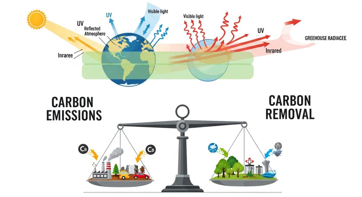
- Thermodynamic Balance: Net-zero requires a strict 1:1 balance between emitted greenhouse gases and verified atmospheric removal.
- Process Integration: Post-combustion carbon capture (PCC) introduces significant thermal penalties that must be integrated into existing steam cycles.
- Fugitive Emissions: Eliminating small-scale leaks in piping networks is just as critical as decarbonizing major combustion stacks.
Greenhouse Effect and Net Zero Carbon Emission Realities
[Atmospheric Radiative Forcing]: The net change in the irradiance energy balance of the Earth system measured in watts per square meter, which dictates the scale of industrial carbon mitigation required under international climate frameworks.
To solve the net-zero equation, we must first understand the radiative physics of the greenhouse effect. Solar radiation enters the Earth’s atmosphere primarily as shortwave ultraviolet and visible light (wavelengths between 0.2 and 3.0 micrometers). The Earth absorbs this energy and re-emits it as longwave infrared radiation (wavelengths between 4.0 and 50 micrometers).
Greenhouse gases (GHGs) such as carbon dioxide (CO2), methane (CH4), and nitrous oxide (N2O) possess molecular structures that allow them to absorb these longwave thermal photons. When a CO2 molecule absorbs infrared radiation at its primary absorption bands (specifically around 15 micrometers), it undergoes vibrational and rotational transitions, subsequently re-radiating that thermal energy in all directions—including back down to the Earth’s surface.
The mathematical relationship governing radiative forcing (Delta F) due to changes in CO2 concentration is expressed by the simplified IPCC formula:
Where:
• Delta F is the radiative forcing in Watts per square meter (W/m²).
• alpha is a constant equal to 5.35.
• C is the current atmospheric CO2 concentration (currently ~420 ppm).
• C_0 is the pre-industrial reference concentration (~280 ppm).
To halt this radiative forcing increase, we must drive net anthropogenic emissions to zero. In process engineering, this is managed via post-combustion carbon capture (PCC) systems. The most mature technology utilizes chemical absorption with amine solvents. The chemical reaction between CO2 and Monoethanolamine (MEA) is an equilibrium-driven process:
This reaction runs forward in an absorber column at 40°C to 60°C. The rich solvent is then pumped to a stripper column, where it is heated to 120°C to 140°C using steam from the plant’s reboiler to reverse the reaction, releasing pure CO2 gas for compression and geological sequestration.
As piping engineers, we must design these systems to handle highly corrosive amine solutions, requiring the use of stainless steel (such as 316L) instead of standard carbon steel in the rich-solvent piping loops. We must also design for the massive pressure drops associated with high-volume flue gas ducting.
Global Warming Potentials and Industrial Emission Factors
[Global Warming Potential]: A relative measure of how much heat a greenhouse gas traps in the atmosphere relative to carbon dioxide over a specific time horizon, governing compliance with EPA and GHG Protocol standards.
To design effective net-zero pathways, we must quantify the impact of different gas species. The table below outlines the Global Warming Potentials (GWP) and typical industrial sources of the primary greenhouse gases regulated under the Greenhouse Gas Protocol.
| Greenhouse Gas | Chemical Formula | Atmospheric Lifetime (Years) | GWP (100-Year Horizon) | Primary Industrial Source |
|---|---|---|---|---|
| Carbon Dioxide | CO2 | Variable (100-1000) | 1 | Fossil fuel combustion, cement calcination |
| Methane | CH4 | 12 | 28 – 36 | Natural gas pipeline leaks, wastewater treatment |
| Nitrous Oxide | N2O | 114 | 265 – 298 | Nitric acid production, fertilizer manufacturing |
| Sulfur Hexafluoride | SF6 | 3200 | 23500 | Electrical switchgear insulation, GIS systems |
Achieving net-zero requires deploying specific engineering technologies across different process units. This matrix maps key decarbonization technologies, their operational parameters, and the governing engineering standards.
| Technology | Primary Application | Typical Efficiency (%) | Key Design Parameter | Governing Standard |
|---|---|---|---|---|
| Amine Scrubbing (PCC) | Flue gas decarbonization | 85% – 95% | Liquid-to-gas (L/G) ratio, reboiler duty | ISO 14064-1 |
| Direct Air Capture (DAC) | Atmospheric CO2 removal | N/A (Removal) | Pressure drop across solid sorbent beds | ASME PTC 50 |
| Oxy-Fuel Combustion | New-build power & cement | > 98% | Oxygen purity, flame temperature control | ASME B31.3 (Oxygen Service) |
| Hydrogen Fuel Switching | Industrial kiln & boiler heating | 100% (Scope 1 reduction) | Hydrogen embrittlement, flashback velocity | ASME B31.12 |
Industrial Carbon Footprint Verification Checklist
[Carbon Footprint Verification]: A systematic auditing process to quantify, validate, and report an industrial facility’s direct and indirect greenhouse gas emissions in compliance with the GHG Protocol Corporate Standard.
Before claiming progress toward net-zero, an industrial facility must establish a rigorous, auditable baseline. In my field experience, many plants fail their third-party audits because they overlook minor emission sources or use incorrect emission factors. Use this checklist to verify your facility’s carbon accounting system.
Site Verification Checkpoints:
-
Scope 1: Direct Combustion Verification
Calibrate all fuel flow meters on boilers, gas turbines, and process heaters in accordance with EPA 40 CFR Part 75. Ensure fuel gas composition is analyzed via gas chromatography to determine precise carbon content.
-
Scope 1: Fugitive Emissions Audit (LDAR)
Implement a Leak Detection and Repair (LDAR) program using EPA Method 21 portable VOC analyzers or Optical Gas Imaging (OGI) cameras to detect and quantify methane leaks from valve packing, flanges, and compressor seals.
-
Scope 2: Indirect Electricity Accounting
Collect utility billing data and apply the correct regional grid emission factors (e.g., eGRID factors in the US) to calculate indirect emissions from purchased electricity and steam.
-
Scope 3: Supply Chain & Logistics Baseline
Map upstream emissions from purchased raw materials and downstream emissions from product transport. Use life-cycle assessment (LCA) software compliant with ISO 14044.
-
Continuous Emissions Monitoring Systems (CEMS)
Verify that stack CEMS are calibrated daily for CO2, NOx, and SO2 concentration, and that volumetric flow rate monitors are functioning correctly to prevent under-reporting of mass emission rates.
Greenhouse Effect and Net Zero Carbon Emission Engineering
[Industrial Decarbonization Engineering]: The application of chemical process optimization, waste heat recovery, and carbon capture technologies to eliminate point-source greenhouse gas emissions from heavy manufacturing facilities.
Field Case Study: Real-World Application
By optimizing the process integration and structural piping design, we successfully captured 90% of the flue gas CO2 (approximately 3 million tons of CO2 per year) while limiting the net power output reduction to just 12%. The captured CO2 was compressed to a supercritical state (140 bar) and transported via a carbon steel pipeline compliant with ASME B31.4 to a deep saline aquifer for permanent geological storage, successfully demonstrating a viable pathway to net-zero operations.
Frequently Asked Engineering Questions
What is the difference between carbon-neutral and net-zero?
How does the greenhouse effect physically trap heat?
What are the primary engineering challenges in amine-based carbon capture?
How do Scope 1, Scope 2, and Scope 3 emissions differ?
What role does green hydrogen play in achieving net-zero carbon emissions?
How are fugitive methane emissions quantified and controlled in piping systems?
===

Complete Course on
Piping Engineering
Check Now
Key Features
- 125+ Hours Content
- 500+ Recorded Lectures
- 20+ Years Exp.
- Lifetime Access
Coverage
- Codes & Standards
- Layouts & Design
- Material Eng.
- Stress Analysis
📚 Recommended Resources: greenhouse effect and net zero carbon emission
Related posts:
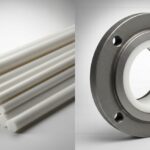
![Comparison of raw PTFE material and an industrial PTFE-lined steel pipe flange]()
Teflon vs PTFE: Major Differences in Industrial Piping Applications
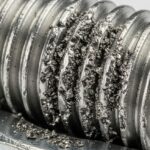
![Severe metal galling damage on a stainless steel threaded bolt and nut.]()
What is Metal Galling and How to Prevent It
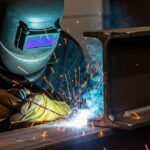
![Certified welder performing structural welding repair on a heavy steel beam with sparks flying.]()
Mastering Industrial Welding Repair Procedures for Structural Integrity
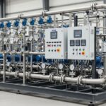
![A fully assembled industrial pump skid system with stainless steel piping and control panels in a factory.]()
What is an Industrial Pump Skid and Its Key Advantages?
![Side-by-side comparison of an industrial flow meter and a digital flow transmitter installed on a pipeline.]()
Flow Transmitter vs Flow Meter: Key Differences Explained
![Wireless vibration sensor mounted on an industrial electric motor for condition monitoring.]()
What is Vibration Monitoring and Why is it Important?