How Anti-Corrosive Composites Protect Critical Oil and Gas Assets
In my 20 years of piping engineering, I have watched carbon steel pipelines succumb to aggressive sour service environments within months. The constant battle against wet carbon dioxide, hydrogen sulfide, and microbiologically influenced corrosion costs the oil and gas industry billions of dollars annually. When we rely solely on chemical inhibitors or expensive corrosion-resistant alloys, we are often just delaying the inevitable.
That is why the shift toward non-metallic piping systems is one of the most significant transitions I have witnessed in my career. By utilizing advanced polymer matrix composites, we eliminate the fundamental electrochemical reactions that cause metallic corrosion. These systems do not just resist degradation; they redefine the lifecycle economics of offshore platforms, produced water lines, and downhole tubing.
- Complete elimination of galvanic and electrochemical corrosion mechanisms.
- Up to seventy percent reduction in structural weight compared to carbon steel.
- Lower friction factors leading to reduced pumping power requirements over the asset life.
- Design lifetimes exceeding twenty-five years with minimal chemical inhibition programs.
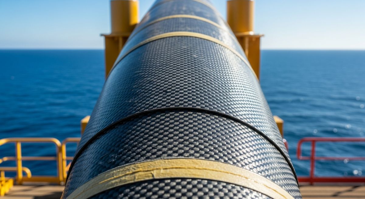
[Composite Material Performance]: The comparative structural and chemical superiority of fiber-reinforced polymers over traditional metallic alloys, specifically engineered to eliminate electrochemical oxidation in aggressive sour service environments under ISO 14692 and ASME NM.2 standards.
Metallic corrosion is an electrochemical process. When carbon steel is exposed to water containing dissolved carbon dioxide (sweet service) or hydrogen sulfide (sour service), galvanic cells form on the metal surface. This leads to rapid pitting, stress corrosion cracking, and hydrogen embrittlement.
In contrast, ISO 14692 compliant Glass Reinforced Epoxy (GRE) and Glass Reinforced Vinyl Ester (GRVE) systems consist of inert glass fibers embedded in a cured thermosetting resin matrix. Because these materials are electrical insulators, they cannot support galvanic cells. The chemical resistance is determined by the polymer matrix, which acts as a barrier preventing corrosive ions from reaching the load-bearing glass fibers.
In my experience, engineers often forget that the axial thermal expansion coefficient of GRE is up to three times higher than that of carbon steel. While the low elastic modulus of composites reduces the resulting thermal thrust forces, unguided piping runs can experience severe buckling if thermal expansion joints or loops are not correctly calculated and installed.
Calculating Minimum Wall Thickness for Composite Piping
To design a safe composite piping system, we must calculate the minimum structural wall thickness based on long-term hydrostatic strength. Unlike isotropic metals, composites are anisotropic; their properties vary with fiber orientation.
According to standard design practices, the minimum structural wall thickness is calculated using the following formula:
Where:
- t_min = Minimum structural wall thickness (mm)
- P_d = Internal design pressure (MPa)
- D_o = Outside diameter of the pipe (mm)
- S_lths = Long-Term Hydrostatic Strength of the composite (MPa) at design temperature
- f_part = Partial design factor (typically 0.5 for hydrocarbon service to account for fatigue and aging)
Let us walk through a practical project scenario. Suppose we are designing an 8-inch (outside diameter of 219.1 mm) produced water line operating at a design pressure of 5.0 MPa and a temperature of 65°C. The manufacturer provides a qualified Long-Term Hydrostatic Strength (S_lths) of 120 MPa for their GRE pipe.
2 * f_part * S_lths = 2 * 0.5 * 120 = 120 MPa
Step 2: Apply the full formula
t_min = (5.0 * 219.1) / (120 + 5.0)
t_min = 1095.5 / 125
t_min = 8.76 mm
Therefore, the minimum structural wall thickness required for this service is 8.76 mm. Any additional liner thickness designed for erosion protection must be added to this value to obtain the total nominal wall thickness.
Designing Anti-Corrosive Composites for High Pressures
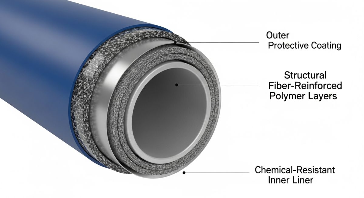
[High-Pressure Composite Design]: The systematic engineering of fiber orientation, resin chemistry, and wall thickness profiles to withstand extreme internal pressures and external loads in deepwater oil and gas applications.
When dealing with high-pressure applications, filament winding angles play a critical role. A winding angle of approximately 55 degrees relative to the pipe axis provides the optimum balance between hoop strength and axial strength. This is because the hoop stress in a pressurized cylinder is exactly twice the axial stress.
For ultra-high-pressure applications, such as downhole tubing or deepwater flowlines, carbon fibers are substituted for glass fibers. Carbon-reinforced epoxy composites offer significantly higher tensile modulus and fatigue resistance, allowing them to operate safely at pressures exceeding 100 MPa.
| Material System | Density (kg/m³) | Tensile Strength (MPa) | Thermal Conductivity (W/m·K) | Max Temp Limit (°C) | Corrosion Resistance |
|---|---|---|---|---|---|
| Glass Reinforced Epoxy (GRE) | 1,800 – 2,000 | 200 – 350 | 0.35 | 110 | Excellent (H2S, CO2, Brine) |
| Glass Reinforced Vinyl Ester (GRVE) | 1,700 – 1,900 | 150 – 250 | 0.30 | 85 | Excellent (Acids, Alkalis) |
| Carbon Reinforced Epoxy (CRPE) | 1,500 – 1,600 | 600 – 1,200 | 1.20 | 150 | Outstanding (All Media) |
| Carbon Steel (API 5L X65) | 7,850 | 535 (Yield) | 50.00 | 400 | Poor (Requires Coating/Inhibitors) |
| Acronym / Entity | Full Technical Name | Primary Physical Parameter | Governing Standard Reference |
|---|---|---|---|
| GRE | Glass Reinforced Epoxy | Glass transition temperature (Tg) | ISO 14692 |
| RTP | Reinforced Thermoplastic Pipe | Minimum bend radius (MBR) | API 15HR |
| LTHS | Long-Term Hydrostatic Strength | 97.5% lower confidence limit stress | ASTM D2992 |
| FRP | Fiber Reinforced Polymer | Fiber volume fraction (Vf) | ASME NM.2 |
[Composite Quality Assurance]: The field-level inspection protocol and non-destructive testing sequence required to verify joint integrity, cure state, and structural bonding before hydrotesting.
Unlike carbon steel, where a simple radiographic test can verify weld quality, composite joint verification requires a specialized approach. Adhesive bonding and lamination joints are highly sensitive to environmental conditions during installation. High humidity or low temperatures can prevent the resin from curing completely, leading to catastrophic joint failure during hydrotesting.
-
Verify Bonder Qualifications: Ensure all installation technicians hold valid certifications under ISO 14692 Part 4.
-
Monitor Environmental Conditions: Confirm relative humidity is below eighty-five percent and ambient temperature is at least three degrees Celsius above the dew point before mixing adhesive.
-
Perform Barcol Hardness Testing: Measure the hardness of cured joints using a Barcol impressor to verify that the resin has achieved at least ninety percent of the manufacturer’s specified cure state.
-
Inspect Support Spacing and Contact: Ensure all pipe supports are fitted with elastomeric pads and that support spans match the composite design specification rather than standard steel spacing.
-
Execute Hydrostatic Testing: Pressurize the system slowly at a rate not exceeding 0.1 MPa per second, holding at one point five times the design pressure for a minimum of four hours.
Field Case Study: Real-World Application
An offshore production platform in the North Sea experienced repeated failures of its carbon steel produced water piping. The combination of high salinity, dissolved carbon dioxide, and sulfate-reducing bacteria caused localized pitting rates exceeding four millimeters per year. The operator was forced to shut down production every eighteen months to replace piping spools, resulting in millions of dollars in lost revenue and maintenance costs.
I led the engineering team that replaced the entire produced water system with Glass Reinforced Epoxy (GRE) piping designed to ISO 14692. The lightweight nature of the composite allowed the installation to be completed using the platform’s existing cranes without structural modifications. After ten years of continuous service, ultrasonic inspections revealed zero wall loss, zero joint degradation, and absolutely no internal scaling.
Based on this project, my direct recommendation is to perform a lifecycle cost analysis during the Front-End Engineering Design (FEED) phase of any produced water or seawater system. While the initial material cost of anti-corrosive composites can be higher than carbon steel, the elimination of corrosion inhibitors, reduced weight, and zero maintenance costs typically result in a full return on investment within three years of operation.
Frequently Asked Engineering Questions
What is the maximum operating temperature for GRE piping systems?
How do composites handle water hammer and pressure surges?
Can composite pipes be used for transporting sour crude oil?
How do you protect composite piping from ultraviolet (UV) degradation?
What non-destructive testing (NDT) methods are used for composite joints?
Are composite pipes fire-resistant for offshore platform use?
Complete Course on
Piping Engineering
Check Now
Key Features
- 125+ Hours Content
- 500+ Recorded Lectures
- 20+ Years Exp.
- Lifetime Access
Coverage
- Codes & Standards
- Layouts & Design
- Material Eng.
- Stress Analysis