Rigid Struts: Definition, Applications, and Modeling in Caesar II
In my 20-plus years of executing piping stress analysis for high-pressure petrochemical plants, I have seen many engineers struggle with selecting the right restraint types. When thermal movements are large and space is tight, standard rigid hangers or guides often fall short. That is where rigid struts come into play. These pin-to-pin structural components act as double-acting restraints, handling both tension and compression along their axis while allowing the piping system to rotate freely.
Modeling these components accurately in software is not just about clicking a button. It requires a deep understanding of structural mechanics, local stiffness, and directional vectors. In this guide, I will share my personal field-tested strategies for configuring rigid struts in Caesar II, ensuring your stress models match real-world physical behavior.
What You Will Learn in This Guide
- The mechanical differences between rigid struts, hangers, and snubbers.
- Step-by-step configuration of double-acting restraints and directional vectors in Caesar II.
- How to calculate and input local structural stiffness to avoid over-optimistic stress results.
- Field verification steps to ensure physical struts do not bind during thermal expansion.
How to Model Rigid Struts in Caesar II
When we model a rigid strut, we are simulating a physical assembly consisting of a pipe attachment (clamp), an extension piece (usually a heavy-wall pipe or solid bar), and a structural attachment (welded bracket). Because both ends utilize spherical bearings or pins, the strut only resists loads along its longitudinal axis. It offers zero resistance to bending or torsion.
In Caesar II, a common mistake is modeling a strut as a simple rigid translational restraint (e.g., a simple “Y” or “X” restraint). This ignores the angular swing of the strut as the pipe moves thermally. If the pipe moves perpendicular to the strut axis, the strut swings through an arc, causing a secondary displacement along its axis. This is known as the “arc-swing effect.”
Mathematical Formulation of Strut Behavior
To evaluate whether a rigid strut is operating within safe limits, we must calculate its angular offset during thermal expansion. According to MSS SP-58, the maximum recommended swing angle for a rigid strut is 4 degrees. This prevents excessive lateral forces on the pipe clamp and structural bracket.
The angular offset (theta) in radians can be approximated using the lateral displacement (dx) perpendicular to the strut axis and the nominal length of the strut (L):
For small angles, this can be simplified to:
If your calculated angle exceeds 4 degrees, you must either increase the strut length (L) or relocate the strut to a point with lower lateral thermal movement.
In my experience, accepting the default “infinite stiffness” in Caesar II for rigid struts leads to highly inaccurate load distributions. Real struts have a finite stiffness determined by the elasticity of the rod, the clamp, and the structural steel backing. Always input the manufacturer-provided stiffness (typically ranging from 50,000 to 150,000 lb/in or 8,750 to 26,250 N/mm) to obtain realistic nozzle loads and pipe stresses.
Step-by-Step Caesar II Input Configuration
To model a rigid strut in Caesar II, follow this precise sequence:
- Select the node where the strut clamp is physically attached to the pipe.
- Double-click the Restraints check box in the piping input screen.
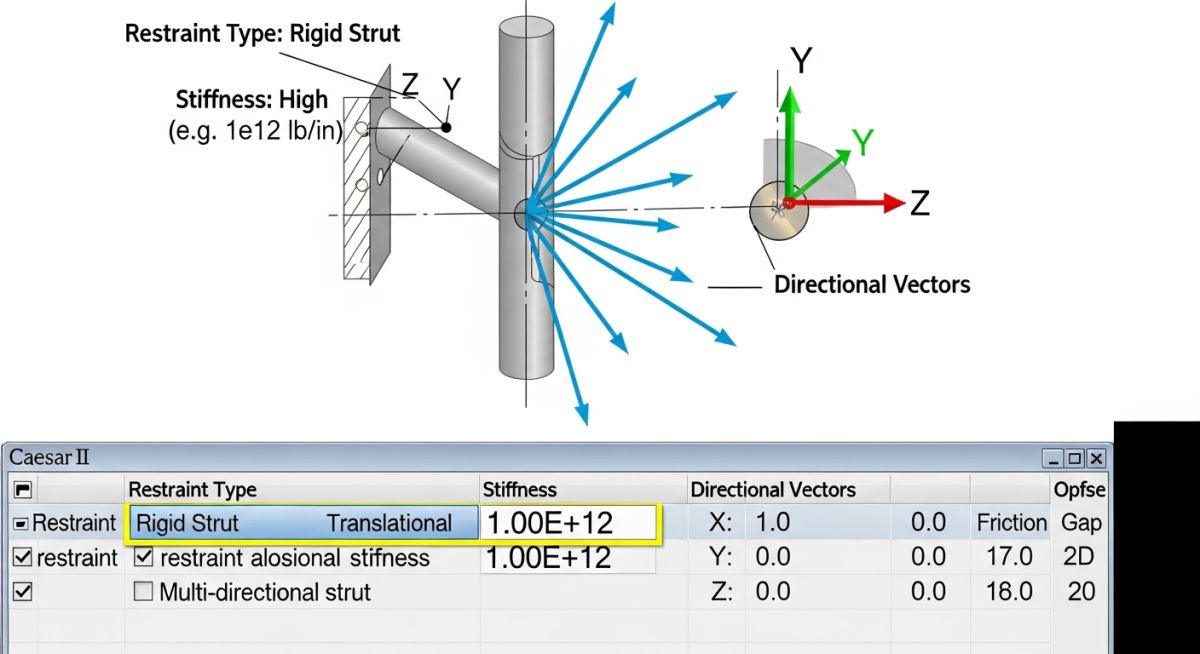
- In the Restraint type dropdown, select Double-Acting (or Rod). Do not use a simple guide unless you are certain lateral movement is zero.
- Define the directional vector. If the strut is inclined, enter the exact direction cosines (Vx, Vy, Vz) calculated from your structural drawings.
- Input the Stiffness value. Refer to the support manufacturer’s catalog (e.g., Anvil, Lisega) for the specific strut size selected.
- Specify the Gap as zero, as rigid struts are pre-loaded and pinned with zero clearance.
The table below outlines standard rigid strut sizes, their typical load capacities, and maximum allowable lateral displacements based on a standard 1000 mm (approx. 40 inches) pin-to-pin length to maintain the 4-degree swing limit under MSS SP-58.
| Strut Size / Model | Max Tension Load (kN) | Max Compression Load (kN) | Typical Stiffness (kN/mm) | Max Lateral Travel (mm) |
|---|---|---|---|---|
| Size 1 (Light Duty) | 12.5 | 10.0 | 15.0 | 69.8 |
| Size 2 (Medium Duty) | 35.0 | 28.0 | 30.0 | 69.8 |
| Size 3 (Heavy Duty) | 80.0 | 65.0 | 55.0 | 69.8 |
| Size 4 (Extra Heavy) | 150.0 | 120.0 | 90.0 | 69.8 |
This matrix maps the core technical entities, structural acronyms, and physical parameters used when modeling rigid struts in Caesar II, cross-referenced with industry standards.
| Entity / Acronym | Physical Parameter | Caesar II Input Field | Standard Reference |
|---|---|---|---|
| CN (Connecting Node) | Structural attachment point node | CNode | ASME B31.3 |
| Stiffness (K) | Axial spring rate of strut assembly | Stiffness (N/mm or lb/in) | MSS SP-58 |
| Direction Cosines | Spatial orientation vectors (Vx, Vy, Vz) | Vector (X, Y, Z) | Structural Steel Codes |
| Thermal Travel | Perpendicular movement at clamp | Displacement (DX, DY, DZ) | ASME B31.3 Clause 319 |
Even the most perfect Caesar II model can fail if the field installation is sloppy. Over my career, I have seen struts installed backward, pins welded shut, and clamps binding against structural steel. Use this checklist during your next site walkdown to verify that the physical installation matches the design intent of MSS SP-58 and ASME B31.3.
Site Walkdown & QA/QC Checklist
-
Pin-to-Pin Length Verification: Measure the exact distance between the centerlines of the upper and lower pins. Ensure it matches the drawing within a tolerance of +/- 3 mm.
-
Cold-Set Angle Alignment: Verify that the strut is installed at the correct cold-set angle. The angle must not deviate by more than 1 degree from the design drawings.
-
Spherical Bearing Freedom: Physically shake the strut assembly (if safe and depressurized) to ensure the spherical bearings rotate freely. There must be no paint, rust, or weld splatter on the pins.
-
Thread Engagement: Check the sight holes on the strut body to confirm that the threaded rods have sufficient engagement. A minimum of 1.5 times the thread diameter must be engaged.
-
Structural Clearance: Ensure there is at least 50 mm of clear space around the strut clamp and extension rod to allow for the calculated lateral swing without hitting adjacent steel.
Field Case Study: Real-World Application
The Problem: High Nozzle Loads on a Steam Turbine
During a commissioning phase at a combined-cycle power plant, the steam turbine inlet piping was experiencing excessive thermal expansion. The original design utilized standard rigid guides. However, during hot startup, the lateral thermal growth of the 16-inch steam line caused the turbine nozzle loads to exceed the allowable limits specified by ASME B31.3 by over 180%. The rigid guides were binding, converting lateral thermal expansion into a massive axial thrust directly onto the turbine casing.
The Solution: Redesigning with Rigid Struts in Caesar II
I was brought in to troubleshoot the system. I remodeled the piping system in Caesar II, replacing the binding rigid guides with two inclined rigid struts. By using inclined struts, we were able to resolve the thermal expansion vector into manageable components. I input the exact manufacturer stiffness of 85 kN/mm for the struts and modeled the 3.2-degree arc swing. The revised Caesar II model showed a 75% reduction in turbine nozzle loads, bringing them well within the manufacturer’s allowable limits.
The physical modification was executed during a scheduled 48-hour shutdown. We installed two heavy-duty rigid struts with spherical joint ends. When the turbine was restarted and reached its operating temperature of 540 degrees Celsius, the struts performed exactly as modeled, swinging smoothly through their calculated arcs without binding.
My Direct Recommendation: Never rely on simple rigid restraints when dealing with high-temperature, critical equipment connections. Always evaluate the use of inclined rigid struts to redirect thermal forces away from sensitive nozzles.
Frequently Asked Questions on Rigid Struts
What is the primary difference between a rigid strut and a rigid hanger?
Why is the 4-degree swing angle limit so critical for rigid struts?
How do I model an inclined rigid strut in Caesar II?
Can a rigid strut be used to resist seismic or wind loads?
Should I input a gap when modeling a rigid strut in Caesar II?
What codes govern the design and selection of rigid struts?
Complete Course on
Piping Engineering
Check Now
Key Features
- 125+ Hours Content
- 500+ Recorded Lectures
- 20+ Years Exp.
- Lifetime Access
Coverage
- Codes & Standards
- Layouts & Design
- Material Eng.
- Stress Analysis
