What are Pipeline Block Valves and How to Design Stations
In my 20 years of designing pipeline systems across the globe, I have seen how a single design oversight at a valve station can jeopardize an entire transmission network. When you are dealing with high-pressure pipelines stretching hundreds of miles, you cannot simply shut down the entire line for a minor repair or during an emergency. This is where pipeline block valves (PBVs) become the unsung heroes of pipeline integrity.
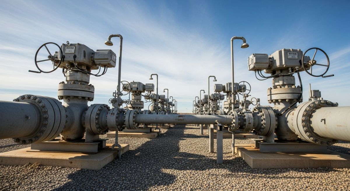
These stations are not just valves dropped into a trench; they are highly engineered facilities designed to withstand extreme environmental conditions, soil settlements, and massive hydraulic forces. In this guide, I will walk you through the exact engineering principles, spacing calculations, and station design practices that I use to ensure these systems operate flawlessly when lives and environments are on the line.
Key Engineering Takeaways
- Understand the regulatory spacing rules governed by ASME B31.4 and ASME B31.8.
- Learn why full-bore API 6D ball and gate valves are mandatory for pigging operations.
- Master the calculations for potential spill volumes and thermal relief bypass design.
- Discover the structural and cathodic protection requirements for valve station piping.
Why We Install Pipeline Block Valves Safely
When designing a pipeline, the spacing of block valves is one of the first critical decisions we make. We do not place them arbitrarily. The spacing is strictly governed by the class location (for gas) or the proximity to high-consequence areas (HCAs) and water bodies (for liquids).
Regulatory Spacing Criteria
For liquid pipelines, ASME B31.4 dictates that block valves must be installed on the upstream and downstream sides of major water crossings, near residential areas, and at maximum intervals of 15 miles (24 kilometers) for industrial zones. For highly volatile liquids (HVLs), this spacing is often reduced to 7.5 miles (12 kilometers) to limit the vapor cloud hazard in the event of a release.
For gas pipelines, ASME B31.8 establishes spacing based on Class Locations, which reflect population density:
- Class 1 (Rural/Desert): Maximum spacing of 20 miles (32 kilometers).
- Class 2 (Semi-rural/Suburban): Maximum spacing of 15 miles (24 kilometers).
- Class 3 (Residential/Commercial): Maximum spacing of 10 miles (16 kilometers).
- Class 4 (Dense Urban with multi-story buildings): Maximum spacing of 5 miles (8 kilometers).
Valve Selection: API 6D Compliance
In my practice, I specify valves manufactured and tested in strict accordance with API Specification 6D. The two primary valve types used are:
- Trunnion-Mounted Ball Valves: These are preferred for most modern pipelines. They offer low operating torque, excellent sealing capabilities, and are inherently double-block-and-bleed (DBB) capable.
- Through-Conduit Slab Gate Valves: These are highly robust and provide a flat, continuous bore when fully open. They are excellent for heavy crude oil or pipelines where mechanical scraping (pigging) is frequent.
Calculating Potential Spill Volume
To justify valve spacing to environmental regulators, we must calculate the maximum potential spill volume between two block valves. The total volume of fluid trapped between two closed valves is calculated using the internal volume of the pipe segment:
Where:
- V: Total isolated volume (cubic meters)
- Di: Inside diameter of the pipe (meters)
- L: Distance between the block valves (meters)
For example, let us calculate the isolated volume for a 30-inch crude oil pipeline with a 0.500-inch wall thickness, where the block valves are spaced 15 miles (24,140 meters) apart:
- Outside Diameter (OD) = 30 inches = 0.762 meters
- Wall Thickness (t) = 0.500 inches = 0.0127 meters
- Inside Diameter (Di) = 0.762 – (2 * 0.0127) = 0.7366 meters
- Cross-sectional Area (A) = (pi / 4) * (0.7366)^2 = 0.4261 square meters
- Total Volume (V) = 0.4261 * 24,140 = 10,286 cubic meters (approximately 64,698 barrels of oil)
This calculation highlights why we must design fast-acting actuators. If a leak occurs, the volume released before the valves close is a function of the leak rate multiplied by the detection and closure time, added to this static inventory volume.
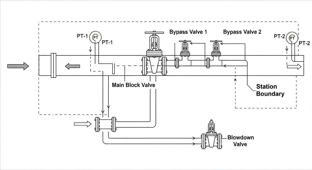
The following table outlines the maximum allowable spacing for pipeline block valves based on the transported medium and the surrounding population density, in compliance with ASME B31.4 and ASME B31.8.
| Pipeline Service | Location Class / Area Type | Max Spacing (Miles) | Max Spacing (KM) | Primary Code Reference |
|---|---|---|---|---|
| Liquid (Crude/Product) | Standard Industrial/Rural | 15 | 24 | ASME B31.4 Section 434.15 |
| Highly Volatile Liquid (HVL) | High-Consequence Area (HCA) | 7.5 | 12 | ASME B31.4 Section 434.15 |
| Gas Transmission | Class 1 (Desert/Rural) | 20 | 32 | ASME B31.8 Section 846.11 |
| Gas Transmission | Class 2 (Suburban) | 15 | 24 | ASME B31.8 Section 846.11 |
| Gas Transmission | Class 3 (Residential) | 10 | 16 | ASME B31.8 Section 846.11 |
| Gas Transmission | Class 4 (Dense Urban) | 5 | 8 | ASME B31.8 Section 846.11 |
This matrix maps the core technical entities, structural acronyms, physical parameters, and standard references required for complete valve station design.
| Entity / Parameter | Acronym | Standard Reference | Design Significance |
|---|---|---|---|
| Double Block and Bleed | DBB | API 6D | Allows verification of seat tightness under full differential pressure. |
| Emergency Shutdown Valve | ESD | ISO 13849 / IEC 61508 | Automated isolation of pipeline segments during overpressure or leak events. |
| Gas-over-Oil Actuator | GOO | Manufacturer Spec | Uses pipeline gas pressure to drive hydraulic fluid for high-torque valve operation. |
| Cathodic Protection Isolation | IJK / MIJ | NACE SP0169 | Monolithic Isolation Joints prevent CP current loss to above-ground station structures. |
| Thermal Relief Valve | TRV | API 526 / API 520 | Prevents overpressurization of trapped liquid in the valve body cavity. |
How to Inspect Pipeline Block Valves Onsite
During my site audits, I often find that installation errors cause more valve failures than manufacturing defects. Use this checklist during your next field inspection to ensure the valve station is built to last.
Pre-Commissioning Field Checklist
Field Case Study: Real-World Application
The Problem: Thermal Binding and Cavity Overpressurization
During a routine summer shutdown on a 24-inch crude oil pipeline in West Texas, operators closed a main pipeline block valve to perform maintenance downstream. Over the course of three days, ambient temperatures reached 104°F (40°C). When maintenance was complete, the operators attempted to open the valve using the electro-hydraulic actuator. The actuator stalled, and the valve remained locked shut.
Upon investigation, we discovered that the crude oil trapped inside the valve body cavity had expanded due to solar radiation. The pressure inside the cavity had risen to over 2,200 psi, while the pipeline design pressure was only 1,480 psi. This extreme pressure forced the seats tightly against the ball, causing severe thermal binding and risking a catastrophic body rupture.
The Outcome: Redesign and Remediation
I was called in to resolve the issue. We immediately depressurized the body cavity using the bleed valve, which allowed the valve to open safely. To prevent this from happening again, we implemented two critical design modifications:
- We replaced the existing solid-seat rings with self-relieving seat rings (single-piston effect upstream, double-piston effect downstream) to allow automatic cavity relief into the upstream line.
- We installed an external thermal relief bypass line equipped with an API 526 relief valve set at 10% above the pipeline design pressure, routing the discharge back to the upstream side.
Since these modifications were implemented, the station has operated through five summer seasons with zero binding incidents and perfect SCADA reliability.
Frequently Asked Engineering Questions
What is the primary difference between a block valve and a standard isolation valve?
Why are full-bore valves mandatory for pipeline block valve stations?
How does a gas-over-oil actuator operate on a pipeline block valve?
What is a double block and bleed (DBB) valve, and why is it used?
How do thermal relief bypasses protect pipeline block valves?
What are the typical maintenance requirements for pipeline block valves?
===
Complete Course on
Piping Engineering
Check Now
Key Features
- 125+ Hours Content
- 500+ Recorded Lectures
- 20+ Years Exp.
- Lifetime Access
Coverage
- Codes & Standards
- Layouts & Design
- Material Eng.
- Stress Analysis