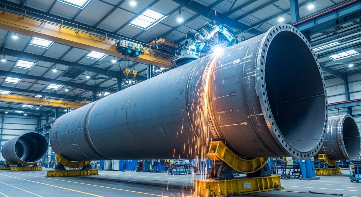
The Critical Pressure Vessel Manufacturing Steps for Industrial Compliance
In my 20-plus years on the heavy fabrication shop floor, I have watched raw steel plates transform into massive, high-pressure reactors destined for refinery service. It is a process where there is absolutely zero margin for error. A single deviation in the rolling sequence, a minor oversight in weld joint preparation, or a poorly executed heat treatment cycle can instantly scrap a two-hundred-thousand-dollar shell plate.
Understanding the exact sequence of fabrication is not just an academic exercise; it is a fundamental requirement for ensuring plant safety and asset longevity. When we talk about high-pressure containment, we are dealing with stored energy levels that can easily level an entire industrial facility. That is why every step of the fabrication process must be executed with surgical precision and fully documented under the watchful eye of Authorized Inspectors.
Key Takeaways From My Shop Floor Experience
- ASME Section VIII compliance is established during the initial design and material receiving phases, not during final inspection.
- Plate rolling requires precise compensation for material springback and fiber elongation to prevent out-of-roundness.
- Welding procedures (WPS) must match the exact metallurgy and heat-treatment requirements of the base metal.
- Non-destructive testing (NDT) is a progressive process that must be integrated into every stage of fabrication.
- Post-weld heat treatment (PWHT) relieves residual stresses that cause stress corrosion cracking in corrosive process environments.
Mastering the Pressure Vessel Manufacturing Steps
The journey of fabricating a pressure vessel begins long before the first arc is struck. It starts with rigorous engineering calculations and material selection. In my practice, I always emphasize that the integrity of the vessel is directly tied to the traceability of its components. Every plate, nozzle, flange, and welding consumable must be fully traceable to its original Mill Test Report (MTR) in compliance with ASME Section VIII Division 1.
Step 1: Material Verification and Traceability
Before any fabrication begins, the quality control team must verify the material specifications. For carbon steel vessels, SA-516 Grade 70 is the industry workhorse due to its excellent tensile strength and notch toughness at moderate to low temperatures. For corrosive services, we often specify SA-240 Type 316L stainless steel or clad plates. The heat numbers stamped on the plates must be transferred and recorded before any cutting occurs. This ensures that even after the vessel is completed, we can trace every square inch of the pressure boundary back to the specific steel mill melt.
Step 2: Cutting and Edge Preparation
Once the materials are verified, the plates are cut to size. We typically use CNC plasma arc cutting or oxy-fuel cutting for carbon steels, while waterjet or plasma cutting is preferred for stainless steels to prevent carbide precipitation. Edge preparation is a critical sub-step. The weld joint geometry (typically a single-V, double-V, or U-groove) must be machined or ground to precise angles. According to ASME Section VIII Div 1 UW-3, the joint category dictates the required weld preparation and subsequent non-destructive examination.
Step 3: Plate Rolling and Shell Forming
The cut and pre-bent plates are fed into heavy-duty three-roll or four-roll plate bending machines. The operator must carefully calculate the required plate length to achieve the target inside diameter while accounting for material thinning and fiber elongation.
Engineering Calculation for Shell Plate Rolling:
To find the exact flat length (L) of a plate required to roll a cylinder:
Where:
– Di = Inside diameter of the shell (e.g., 1500 mm)
– t = Nominal plate thickness (e.g., 32 mm)
– Mean Diameter (Dm) = Di + t = 1532 mm
– Theoretical Length = 3.14159 * 1532 = 4812.9 mm
In practice, we add a trimming allowance of 50 to 100 mm to the plate ends. This allows us to cut off the unbent flat ends that inevitably occur at the edges of the rolling machine rolls, ensuring a perfect circle when the longitudinal seam is fit up.
Step 4: Head Forming (Dishing and Flanging)
Pressure vessel heads (end caps) are formed using specialized hydraulic presses and flanging machines. The most common shapes are 2:1 semi-ellipsoidal, torispherical, and hemispherical. Hemispherical heads are the most efficient, requiring half the thickness of a cylindrical shell for the same design pressure, but they are the most expensive to manufacture due to the deep drawing process. During dishing, the plate undergoes significant thinning, particularly at the knuckle radius. Designers must specify a starting plate thickness that accounts for this thinning to ensure the minimum design thickness is maintained after forming.
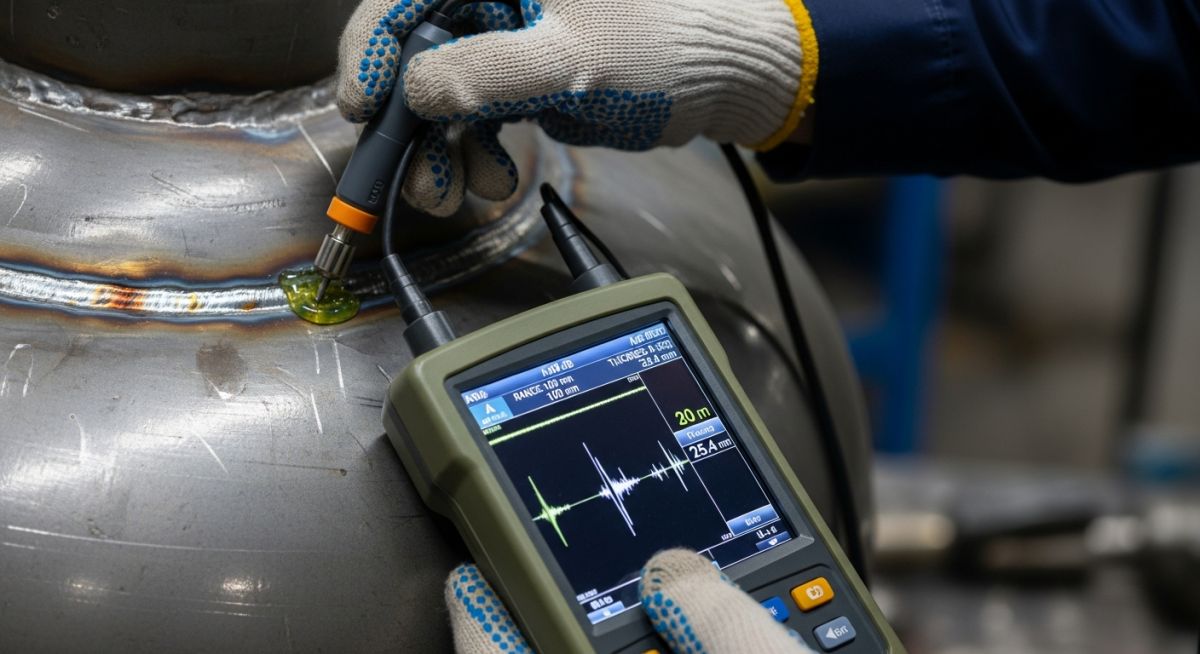
Step 5: Longitudinal and Circumferential Welding
With the shells rolled and the heads formed, the components are aligned for welding. This is where the skill of the welder and the robustness of the Welding Procedure Specification (WPS) are tested. Longitudinal seams are welded first, followed by the circumferential seams that join the shell courses together and attach the heads. Submerged Arc Welding (SAW) is typically used for the main seams due to its high deposition rate and excellent weld quality. For nozzle-to-shell welds, Gas Tungsten Arc Welding (GTAW) or Shielded Metal Arc Welding (SMAW) is preferred for better control in tight geometries.
The following table outlines the critical material specifications, pre-heat requirements, and maximum allowable out-of-roundness tolerances per ASME Section VIII Division 1 UG-80.
| Material Spec | Common Application | Min Pre-heat Temp | PWHT Required | Max Out-of-Roundness (UG-80) |
|---|---|---|---|---|
| SA-516 Gr. 70 | Moderate/Low Temp Carbon Steel | 10°C to 79°C (based on thickness) | Yes, if thickness > 38mm | 1% of nominal diameter |
| SA-387 Gr. 11 | High Temp Chrome-Moly Steel | 150°C | Always required | 1% of nominal diameter |
| SA-240 Type 316L | Corrosive Service Stainless Steel | None (maintain low interpass) | No (except in special services) | 1% of nominal diameter |
This matrix maps the primary manufacturing phases to their corresponding ASME code references, key physical parameters, and verification methods.
| Manufacturing Phase | ASME Code Reference | Key Physical Parameter | Verification Method |
|---|---|---|---|
| Plate Cutting | ASME UG-76 & UG-77 | Bevel Angle & Heat Number Transfer | Visual Inspection & Die Stamping |
| Shell Rolling | ASME UG-80 | Ovality & Circumference | Sweep Templates & Pi-Tape Measurement |
| Longitudinal Welding | ASME UW-35 | Weld Reinforcement Height | Radiographic Testing (RT) / UT |
| PWHT | ASME UCS-56 | Heating Rate, Hold Temp, Cooling Rate | Thermocouple Chart Recording |
Verifying the Pressure Vessel Manufacturing Steps
Quality control is not a final step; it is an ongoing discipline. On my projects, we establish strict “hold points” where fabrication must stop until the Quality Control Inspector (QCI) and the Authorized Inspector (AI) sign off on the progress. Below is the exact checklist I use to verify that the pressure vessel manufacturing steps are executed correctly.
Mandatory Quality Control Hold Points
-
Material Receiving & Traceability: Verify that all plate heat numbers match the Mill Test Reports (MTRs). Ensure no laminations or surface defects are present on the plates.
-
Edge Preparation & Bevel Angle: Check the bevel angle (typically 30 to 37.5 degrees) using a weld gauge. Ensure the root face (land) is uniform and free of slag or scale.
-
Shell Ovality & Roundness: Measure the difference between the maximum and minimum inside diameters at any cross-section. It must be less than 1% of the nominal inside diameter per ASME UG-80.
-
Weld Fit-up & Alignment: Verify the root gap and alignment offset of the longitudinal and circumferential joints. Ensure the offset does not exceed the limits specified in ASME UW-33.
-
Preheat & Interpass Temperature: Monitor and record preheat temperatures using tempilstiks or infrared pyrometers to prevent hydrogen-induced cracking.
-
Post-Weld Heat Treatment (PWHT): Verify thermocouple placement and review the furnace temperature-time chart to ensure the heating, holding, and cooling rates comply with ASME UCS-56.
Field Case Study: Real-World Application
During the fabrication of a 50mm thick carbon steel wash column, the fabrication shop rolled the shell plates without performing the mandatory pre-bending step on the plate edges. The longitudinal seam was fit up and welded using Submerged Arc Welding (SAW). Upon final dimensional inspection, the AI-assisted laser scanner flagged a flat spot along the longitudinal weld seam. The out-of-roundness (ovality) deviation was measured at 1.8%, which significantly exceeded the 1% limit allowed by ASME Section VIII UG-80. This deviation created a high localized bending stress concentration that would have compromised the vessel’s fatigue life in cyclic service.
To salvage the shell course, we had to gouge out the completed longitudinal weld, re-heat the plate edges, and re-roll the shell using a specialized heavy-duty plate bending machine equipped with custom radius templates. The shell was then re-welded, and 100% radiography was performed to ensure weld integrity. This rework cost the project twelve days of schedule delay and forty-five thousand dollars in labor and consumables.
As a corrective action, I implemented a mandatory hold point for template verification immediately after pre-bending and initial rolling, before any tack welding. This simple step completely eliminated flat-spot reworks on all subsequent shell courses.
My recommendation for any engineering manager overseeing pressure vessel fabrication is to never rely solely on final dimensional checks. Implement progressive template checks during the rolling process. It is far easier to correct a flat spot while the plate is still in the rolls than to gouge out a completed weld on a heavy-wall shell.
Frequently Asked Engineering Questions
What is the maximum allowable out-of-roundness for pressure vessels?
When is Post-Weld Heat Treatment (PWHT) mandatory?
How does ASME Section VIII distinguish between Category A and Category B weld joints?
What is the difference between pneumatic and hydrostatic testing?
Why is SA-516 Grade 70 the most common carbon steel plate?
What NDT methods are required for 100% radiography (RT-1) vessels?
Complete Course on
Piping Engineering
Check Now
Key Features
- 125+ Hours Content
- 500+ Recorded Lectures
- 20+ Years Exp.
- Lifetime Access
Coverage
- Codes & Standards
- Layouts & Design
- Material Eng.
- Stress Analysis