Table of Contents
Understanding DN and PN Numbers for Pipes and Class Ratings
In my 20+ years of active piping engineering on global oil, gas, and power projects, I have seen brilliant young engineers make costly mistakes simply because they did not understand how metric and imperial piping systems interface. I still remember a major refinery expansion in Rotterdam where a junior engineer assumed an ASME Class 150 flange would bolt directly to an EN PN 16 flange because “the sizes looked about the same.” The resulting mismatch halted a critical hydrotest, costing the project thousands of dollars in hot-work modifications.
Understanding the exact relationship between DN, PN, and ASME Class ratings is not just academic; it is a fundamental field requirement. Let me walk you through the exact engineering principles, calculations, and conversion matrices that will keep your designs safe, compliant, and perfectly aligned on-site.
Key Engineering Takeaways
- DN (Nominal Diameter) is a dimensionless rating system that corresponds closely to the pipe’s outer diameter in millimeters, but is not an exact physical measurement.
- PN (Pressure Nominal) defines the maximum allowable working pressure in bar at a reference temperature of 20 degrees Celsius.
- ASME Class Ratings (Class 150, 300, etc.) do not have a direct, linear mathematical conversion to PN ratings because their pressure-temperature curves are derived from different material groups and design codes.
- Flange Mismatches are a major source of field failures; bolt circle diameters and hole counts differ significantly between ASME and EN/ISO standards.
Understanding DN and PN Numbers for Pipes in Industrial Systems
To design robust piping systems, we must look at the standards that govern these designations. The metric system relies heavily on ISO 6708 for Nominal Diameter (DN) and ISO 7268 for Pressure Nominal (PN). In contrast, the imperial system used predominantly in North America relies on NPS (Nominal Pipe Size) and Class ratings governed by ASME B16.5 and ASME B36.10M.
The Mechanics of DN (Nominal Diameter)
DN is an alphanumeric designation for size which is common to all components in a piping system other than components designated by outside diameters or by thread size. It is a convenient round number for reference purposes. For example, when we specify a DN 150 pipe, the actual outside diameter (OD) of the pipe is 168.3 mm. The internal diameter (ID) will vary depending on the wall thickness (schedule) of the pipe.
This is a critical point: the DN number is neither the exact internal diameter nor the exact external diameter, but rather a standardized reference size that ensures all valves, flanges, and fittings of the same DN will physically align and connect.
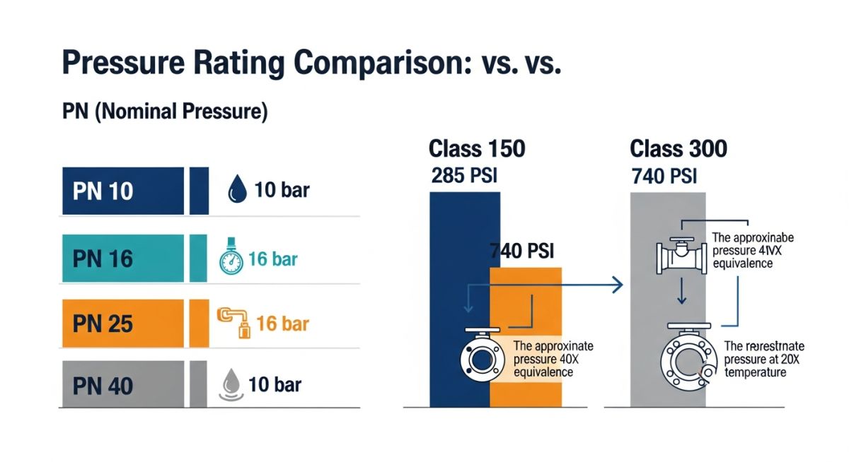
The Mechanics of PN (Pressure Nominal)
PN is a rating system designated by the letters PN followed by a dimensionless number, which indicates the maximum allowable pressure of a piping component at a reference temperature of 20 degrees Celsius. For instance, a PN 16 rating indicates that the component is designed to operate safely at a maximum pressure of 16 bar (approximately 1.6 MPa or 232 psi) when the operating temperature is 20 degrees Celsius.
Pressure-Temperature Derating Calculation
To calculate the actual maximum allowable working pressure (P_T) at an elevated temperature (T), we use the derating factor derived from the material’s allowable stress values:
Where:
P_T = Maximum allowable working pressure at design temperature T (bar)
P_PN = Nominal pressure rating (PN value in bar at 20°C)
S_T = Allowable stress of the material at design temperature T (MPa)
S_RT = Allowable stress of the material at room temperature 20°C (MPa)
ASME Class Rating vs. PN Numbers
One of the most common points of confusion in international engineering offices is comparing ASME Class ratings (Class 150, 300, 600, 900, 1500, 2500) with European PN ratings. ASME ratings are based on pressure-temperature limits defined in ASME B16.5, which vary significantly depending on the material group (e.g., Group 1.1 Carbon Steel, Group 2.2 Stainless Steel).
Because of these material-specific curves, there is no single, constant multiplier to convert Class to PN. However, for general comparison and selection of equivalent standard classes, engineers use standardized approximations. For example, Class 150 is generally paired with PN 20, and Class 300 is paired with PN 50.
NPS to DN and Pipe Outside Diameter (OD) Mapping
The table below provides the standard conversion between Nominal Pipe Size (NPS) in inches, Nominal Diameter (DN) in millimeters, and the actual physical outside diameter (OD) according to ASME B36.10M and ISO 6708.
| NPS (Inches) | DN (mm) | Actual OD (Inches) | Actual OD (mm) |
|---|---|---|---|
| 1/2″ | DN 15 | 0.840″ | 21.3 mm |
| 1″ | DN 25 | 1.315″ | 33.7 mm |
| 2″ | DN 50 | 2.375″ | 60.3 mm |
| 3″ | DN 80 | 3.500″ | 88.9 mm |
| 4″ | DN 100 | 4.500″ | 114.3 mm |
| 6″ | DN 150 | 6.625″ | 168.3 mm |
| 8″ | DN 200 | 8.625″ | 219.1 mm |
| 12″ | DN 300 | 12.750″ | 323.9 mm |
ASME Class Rating to PN Rating Comparison
The following table maps the standard ASME Class ratings to their closest equivalent PN ratings as defined in international standards like EN 1092-1 and ISO 7005-1.
| ASME Class Rating | Equivalent PN Rating | Nominal Design Pressure (bar) | Nominal Design Pressure (psi) |
|---|---|---|---|
| Class 150 | PN 20 | 20 bar | 290 psi |
| Class 300 | PN 50 | 50 bar | 725 psi |
| Class 600 | PN 100 | 100 bar | 1450 psi |
| Class 900 | PN 150 | 150 bar | 2175 psi |
| Class 1500 | PN 250 | 250 bar | 3625 psi |
| Class 2500 | PN 420 | 420 bar | 6090 psi |
Technical Mapping & Specifications Matrix
| Entity / Parameter | Primary Standard | Measurement Unit | Key Application Scope |
|---|---|---|---|
| DN (Nominal Diameter) | ISO 6708 | Dimensionless (mm equivalent) | Standardizing physical size of piping components globally. |
| PN (Pressure Nominal) | ISO 7268 / EN 1092-1 | Dimensionless (bar equivalent at 20°C) | Defining pressure limits for European and international systems. |
| NPS (Nominal Pipe Size) | ASME B36.10M / B36.19M | Dimensionless (inch equivalent) | Standardizing physical size in North American systems. |
| ASME Class Rating | ASME B16.5 | Dimensionless (Class 150 to 2500) | Defining pressure-temperature ratings for flanges and fittings. |
Site Verification Checklist for DN and PN Numbers for Pipes
Before releasing any piping system for hydrotesting or commissioning, field engineers must physically verify that the installed components match the design drawings (P&IDs and Isometrics). Use this checklist on-site to prevent catastrophic mismatches.
Field Inspection Checkpoints
-
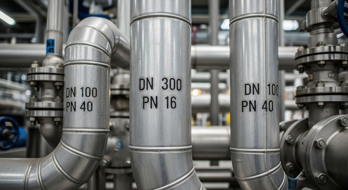
Verify Component Markings: Check that the physical stamp on the pipe body or flange rim matches the design specification (e.g., “DN 100 PN 16” or “4 inch Class 150”).
-
Measure Outside Diameter (OD): Use a vernier caliper to measure the actual OD of the pipe. Ensure it matches the standard metric OD for the specified DN (e.g., DN 50 must have an OD of 60.3 mm).
-
Confirm Flange Bolt Circle Diameter (BCD): Measure the distance between the centers of opposite bolt holes. A DN 100 PN 16 flange has a BCD of 180 mm with 8 holes, whereas an ASME 4″ Class 150 flange has a BCD of 190.5 mm with 8 holes. They will not bolt together!
-
Check Gasket Compatibility: Ensure the gasket dimensions match the specific flange standard. An EN 1514-1 gasket (for PN flanges) must not be used on an ASME B16.21 flange (for Class flanges) due to differences in inner and outer diameters.
-
Review Material Certificates (MTRs): Cross-reference the heat numbers stamped on the pipes with the material test reports to confirm compliance with EN 10216-2 or ASTM A106.
Field Case Study: Real-World Application
The Problem: Flange Mismatch on a Utility Water Line
During the construction of a combined-cycle power plant in Poland, a European EPC contractor procured utility water piping designed to EN standards (DN 150, PN 16). However, the high-pressure pump skid was imported from a US manufacturer, featuring ASME B16.5 Class 150 flanged connections (6″ NPS).
The field installation crew tried to force-fit the DN 150 PN 16 piping directly to the 6″ Class 150 pump flange. Because the bolt circle diameter of the ASME flange (241.3 mm) was larger than the EN flange (240 mm), and the bolt hole sizes differed, the bolts could not be inserted straight. The crew attempted to ream the bolt holes on-site, which compromised the structural integrity of the flange and violated ASME B31.3 code compliance.
When I was called to the site, I immediately halted the installation. Reaming the flange holes had already invalidated the manufacturer’s warranty and safety factor. I designed a custom transition spool piece. One end of the spool featured an EN 1092-1 PN 16 weld-neck flange to match the field piping, while the other end featured an ASME B16.5 Class 150 weld-neck flange to match the pump skid.
We fabricated and hydrotested the transition spool in a controlled shop environment, ensuring full compliance with ASME B31.3. This solution saved the project from a potential catastrophic flange failure during operation and avoided over 120,000 in potential rework and downtime.
My recommendation for all international projects is clear: always map out your piping interfaces during the FEED (Front-End Engineering Design) phase. Never let the field construction crew resolve standard mismatches on-site without engineering approval.
Frequently Asked Engineering Questions
Here are the most common technical questions I encounter regarding DN and PN numbers for pipes and how they interface with imperial standards.
Can you bolt an ASME Class 150 flange directly to an EN PN 16 flange?
What is the exact physical meaning of DN 50?
How does temperature affect the PN rating of a pipe?
Is PN 40 equivalent to ASME Class 300?
What standards govern DN and PN numbers for pipes?
Why does DN not match the internal diameter (ID) of the pipe?
===
Complete Course on
Piping Engineering
Check Now
Key Features
- 125+ Hours Content
- 500+ Recorded Lectures
- 20+ Years Exp.
- Lifetime Access
Coverage
- Codes & Standards
- Layouts & Design
- Material Eng.
- Stress Analysis

📚 Recommended Resources: DN and PN numbers for pipes
Read these Guides


Related posts:
![Super duplex stainless steel piping network on an offshore oil drilling platform.]()
Super Duplex Stainless Steel Oil and Gas Piping Design Guide
![Industrial duplex stainless steel piping system in a chemical processing facility.]()
Understanding Duplex Stainless Steel Properties and Industrial Piping Applications
![A welder performing a critical golden joint weld on an industrial steel pipeline.]()
What is a Golden Joint in Piping Systems?
![A collection of different types of industrial pipes classified by material and size on a storage rack.]()
Comprehensive Guide to Types of Pipes and Industrial Classification Systems
![Industrial piping network with digital overlays representing inch-dia and inch-meter engineering calculations.]()
What are Inch-Dia and Inch-Meter in Piping Systems?
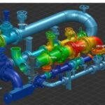
![3D finite element stress analysis model of an industrial piping system showing stress distribution.]()
What Causes Piping System Stresses in Industrial Plants?