Table of Contents
What is Slug Flow? Steps for Slug Flow Analysis and Prevention
In my 20 years of piping engineering, I have seen slug flow rip heavy-duty pipe supports right out of their concrete foundations. It is one of the most destructive phenomena in multiphase pipelines. When gas and liquid travel together through a pipe, they do not always behave nicely. Under certain velocity combinations, the liquid accumulates into a solid plug—a slug—that is propelled forward by high-pressure gas at terrifying speeds.
Every time one of these high-density liquid slugs hits an elbow, it acts like a water hammer, transferring massive momentum to the piping structure. If your piping system is not designed to handle these transient dynamic forces, you are looking at severe piping vibration, fatigue failure of small-bore connections, and structural damage. In this guide, I will share my field-tested approach to analyzing, managing, and preventing slug-induced failures in industrial piping systems.
Key Engineering Takeaways
- Understand the physics behind hydrodynamic, terrain-induced, and pigging-induced slugging.
- Learn how to calculate transient impact forces at piping elbows using momentum change equations.
- Discover the step-by-step workflow for dynamic piping stress analysis using CAESAR II.
- Explore practical mitigation strategies, from slug catchers to targeted piping support modifications.
Complete Course on
Piping Engineering
Check Now
Key Features
- 125+ Hours Content
- 500+ Recorded Lectures
- 20+ Years Exp.
- Lifetime Access
Coverage
- Codes & Standards
- Layouts & Design
- Material Eng.
- Stress Analysis
Why Is Slug Flow Analysis Critical for Piping?
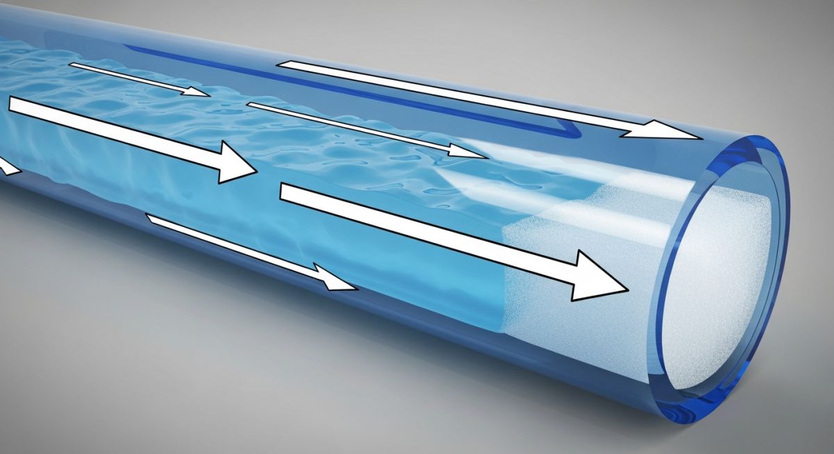
Multiphase Flow Dynamics: Hydrodynamic slugging occurs when high-velocity gas waves over a liquid film grow to bridge the entire pipe cross-section, creating a high-momentum liquid piston. Performing a detailed slug flow analysis allows piping designers to calculate the exact impact forces at elbows and changes in direction, preventing catastrophic fatigue failures and support displacement.
To design a safe piping system, we must first understand the mechanics of the fluid inside. In a multiphase pipeline, slug flow is classified into three primary types based on how the slugs are formed:
- Hydrodynamic Slugging: Formed in horizontal or slightly inclined pipes when the gas velocity is high enough to create waves on the liquid surface. These waves eventually grow, bridge the pipe, and form a fast-moving liquid slug.
- Terrain-Induced Slugging: Occurs in pipelines with undulating topography. Liquid accumulates at the low points (valleys) of the pipeline, blocking the gas flow. Once the gas pressure builds up sufficiently, it pushes the accumulated liquid up the riser as a massive slug.
- Pigging-Induced Slugging: A planned operational event where a pig is launched to clear liquid holdup from the line, pushing a continuous, predictable liquid slug ahead of it.
When a liquid slug travels through a straight pipe, the forces are relatively balanced. However, when the slug encounters a change in direction, such as a 90-degree elbow, it experiences a rapid change in momentum. This change in momentum exerts a transient force on the piping elbow.
In my early career, I saw engineers try to simplify slug loads by applying a static equivalent force. This is a dangerous practice. Slug forces are highly transient and time-dependent. Applying a static multiplier often underestimates the structural response, leading to overloaded anchors and failed guide supports. Always use dynamic time-history analysis for critical multiphase lines.
Calculating the Transient Slug Force
The fundamental equation used to calculate the fluid force acting on an elbow during slug passage is derived from the momentum conservation principle. The force vector is calculated as:
Where:
- F_slug: The dynamic force acting on the elbow (Newtons).
- DLF: Dynamic Load Factor (typically ranges from 1.2 to 2.0, depending on the structural natural frequency and slug rise time).
- rho_mixture: The density of the liquid slug mixture, accounting for entrained gas bubbles (kg/m³).
- A: The internal cross-sectional area of the pipe (m²).
- v_slug: The translational velocity of the slug (m/s).
- theta: The angle of the piping bend (e.g., 90 degrees).
To perform an accurate ASME B31.3 compliance check, these forces must be applied as time-history dynamic loads at each elbow location. The duration of the force application is equal to the time it takes for the slug to pass through the elbow, which is calculated as the slug length divided by the slug velocity.
The table below outlines typical slug flow parameters across different pipeline sizes and their corresponding structural impact levels. These values serve as a preliminary reference during the initial design phase before detailed transient simulation results are available.
| Pipe Size (NPS) | Slug Velocity (m/s) | Liquid Holdup (-) | Dynamic Force Range (kN) | Recommended Support Type |
|---|---|---|---|---|
| 6″ (NPS 6) | 5 to 12 | 0.65 – 0.80 | 5 – 15 | Rigid Struts / Guides |
| 12″ (NPS 12) | 8 to 18 | 0.70 – 0.85 | 25 – 60 | Hold-down Clamps with Teflon Pads |
| 24″ (NPS 24) | 12 to 25 | 0.75 – 0.90 | 120 – 350 | Heavy-duty Anchors & Snubbers |
| 36″ (NPS 36) | 15 to 30 | 0.80 – 0.95 | 400 – 1,200 | Structural Concrete Anchors |
This matrix maps the core technical entities, structural acronyms, and physical parameters involved in a comprehensive slug flow analysis, cross-referenced with industry standards.
| Entity / Parameter | Acronym | Physical Unit | Standard Reference | Engineering Role |
|---|---|---|---|---|
| Dynamic Load Factor | DLF | Dimensionless | ASME B31.3 Appendix F | Amplifies static forces to account for structural resonance. |
| Liquid Holdup | H_L | Fraction (0 to 1) | API RP 14E | Determines the effective density of the moving slug. |
| Translational Velocity | V_T | m/s | OLGA / LedaFlow Output | Governs the kinetic energy and momentum change of the fluid. |
| Allowable Stress Range | S_A | MPa / psi | ASME B31.4 Chapter II | Defines the fatigue limit for cyclic transient slug loading. |
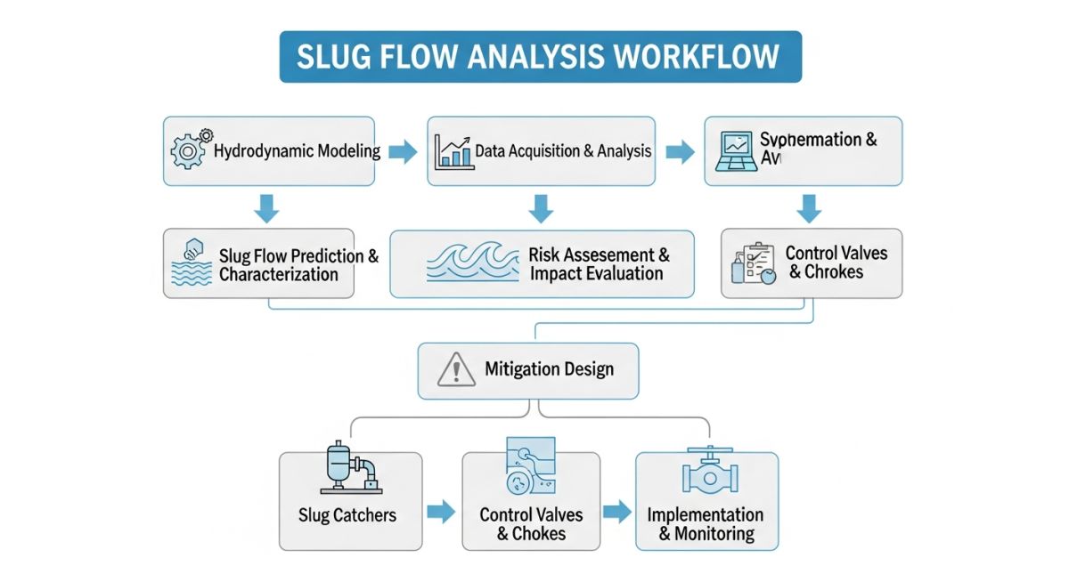
How to Execute a Slug Flow Analysis?
Flow Assurance Verification: Executing a slug flow analysis requires a systematic evaluation of fluid properties, pipeline topography, and transient operating scenarios to identify slug-prone zones. This verification process ensures that piping supports, anchors, and shock absorbers are sized correctly to withstand dynamic momentum changes.
Before finalizing any piping layout carrying multiphase fluids, I run through a strict verification protocol. This checklist ensures that both the process parameters and structural constraints are fully aligned to prevent field failures.
Piping Engineer’s Field Verification Checklist
-
Verify Multiphase Flow Regime: Confirm via multiphase simulation software (such as OLGA) that slug flow is indeed predicted under minimum, normal, and maximum flow rates.
-
Extract Slug Characteristics: Document the maximum slug velocity, slug length, and liquid density. Do not rely on average values; always design for the worst-case envelope.
-
Calculate Dynamic Forces: Apply the momentum equation at all critical 3D changes in direction. Ensure the calculated forces include an appropriate Dynamic Load Factor (DLF).
-
Perform Time-History Analysis: Input the transient force-time profiles into CAESAR II or AutoPIPE. Verify that the piping code stresses comply with ASME B31.3.
-
Inspect Support Rigidity: Ensure that guide supports have zero lateral gap (or a maximum of 1mm) to prevent the pipe from gaining momentum before hitting the support.
-
Validate Anchor Foundations: Cross-check the dynamic reaction forces at anchors with the structural engineering team to ensure the concrete foundations can absorb the cyclic loads.
Field Case Study: Real-World Application
During the commissioning of a 20-inch gas-condensate pipeline in an offshore processing facility, the operations team reported alarming piping vibrations at the riser base. The pipe was physically jumping off its spring hangers, and a small-bore pressure transmitter connection had already sheared off due to fatigue. The process data confirmed that terrain-induced slugging was occurring at the low point of the sea-line riser, sending 15-meter-long liquid slugs crashing into the first platform elbow at 18 m/s.
I was called to the site to lead the emergency engineering task force. We immediately performed a transient slug flow analysis. Using the process parameters, we calculated a dynamic impact force of 185 kN at the riser elbow.
We implemented a two-pronged solution:
- We replaced the standard spring hangers near the elbow with heavy-duty hydraulic snubbers to absorb the dynamic shock loads without restricting thermal expansion.
- We installed a rigid axial anchor block downstream of the elbow, anchored directly into the platform’s primary structural steel.
The dynamic stress analysis in CAESAR II confirmed that the piping stresses dropped from 240% of the allowable limit down to a safe 62% of the ASME B31.3 fatigue limit. The platform has now been operating for over five years without a single vibration-related incident.
This project proved once again that you cannot solve dynamic slugging problems with static thinking. Proper modeling, combined with robust structural anchoring, is the only way to guarantee long-term reliability.
Frequently Asked Engineering Questions
What is the difference between hydrodynamic slugging and terrain slugging?
How does ASME B31.3 govern slug flow design?
What is a typical Dynamic Amplification Factor (DAF) for slug loads?
How do you mitigate slug flow without changing the pipe routing?
Why is liquid holdup important in slug flow analysis?
Can slug flow cause piping fatigue failures?
===FAQ_BLOCK===
Complete Course on
Piping Engineering
Check Now
Key Features
- 125+ Hours Content
- 500+ Recorded Lectures
- 20+ Years Exp.
- Lifetime Access
Coverage
- Codes & Standards
- Layouts & Design
- Material Eng.
- Stress Analysis

📚 Recommended Resources: slug flow analysis
Read these Guides
🎓 Advanced Training


Related posts:
![Industrial worker welding a large structural steel I-beam in a fabrication facility.]()
What is Structural Steel Fabrication and How Does It Work?
![A heavy-duty stainless steel turnbuckle tensioning a structural cable.]()
What is a Turnbuckle and How to Install It?
![Stack of newly manufactured galvanized steel pipes in an industrial warehouse]()
Understanding the Galvanized Pipe Meaning in Modern Piping Systems
![Industrial Alloy 625 piping components in a manufacturing plant]()
What is Alloy 625? Properties, Grades, and Applications of Alloy 625
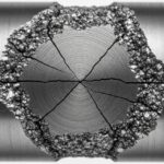
![Close-up of a fractured steel shaft showing metal fatigue beach marks and failure zones.]()
What is Metal Fatigue and How Do Engineers Prevent It?
![Industrial machinery fitted with smart sensors displaying real-time condition-based maintenance data on a digital overlay.]()
What is Condition-Based Maintenance and How Does It Work?