Table of Contents

Guided Cantilever Method for Frame Analysis in Industry
In my experience across EPC and process plant projects, especially while working on pipe racks and multi-level structures in methanol and steel plants, one challenge always comes up—how do you quickly validate load distribution without waiting for a full STAAD or ETABS run?
During early design stages—like your typical option-1 vs option-2 comparison or land parcel layout decisions—you cannot afford to delay structural decisions. This is exactly where I rely on the Guided Cantilever Method to get a fast and surprisingly reliable estimate of axial forces in columns.
Whether it is a tall pipe rack resisting wind loads, a multi-storey equipment support frame, or even a rigid boundary wall under lateral pressure, the behavior closely resembles a vertical cantilever—fixed at the base and bending under load.
- Best suited for quick EPC-stage structural decisions
- Directly applicable to pipe racks and multilevel industrial frames
- Helps estimate column axial forces without full FEM modeling
- Ideal for early-stage load validation and optimization
Interactive Engineering Quiz
Q1: In Guided Cantilever Method, a multistorey frame is assumed to behave like:
Complete Course on
Piping Engineering
Check Now
Key Features
- 125+ Hours Content
- 500+ Recorded Lectures
- 20+ Years Exp.
- Lifetime Access
Coverage
- Codes & Standards
- Layouts & Design
- Material Eng.
- Stress Analysis
How Guided Cantilever Method Actually Works
Guided Cantilever Method: The guided cantilever method models a multistorey frame as a vertical cantilever fixed at its base where axial stress in each column is directly proportional to its distance from the neutral axis, enabling simplified lateral load analysis aligned with conceptual checks from IS 875 and IS 1893.
When I apply this method in pipe rack design or EPC frames, I mentally convert the entire structure into a single cantilever resisting wind or seismic loads. This allows me to estimate how axial forces distribute across columns without opening analysis software.
Step-by-Step Calculation Logic
- Total lateral load is applied at each floor level
- Frame behaves like a cantilever fixed at base
- Neutral axis passes through centroid of column area
- Stress in column ∝ distance from neutral axis
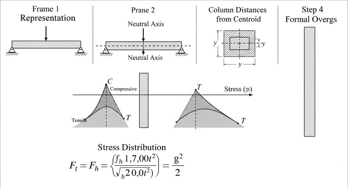
Core Engineering Formula Breakdown
Axial force in column is determined using:
- M = Overturning moment at base
- y = Distance of column from centroid
- I = Moment of inertia of column group
From this stress, axial force in each column is calculated:
In one methanol plant project, I used this method during bid stage to validate column forces across multiple configuration options before final FEM modeling, saving several design cycles.
| Parameter | Description | Site Relevance |
|---|---|---|
| Neutral Axis | Centroid of column system | Defines compression/tension zones |
| Overturning Moment | Lateral load × height | Critical in wind/seismic design |
| Column Distance (y) | Distance from centroid axis | Directly impacts axial stress |
| Moment of Inertia (I) | Resistance to bending | Higher I reduces stress |
| Method | Best Use Case | Accuracy Level | Industrial Relevance |
|---|---|---|---|
| Guided Cantilever Method | Tall frames & pipe racks | Moderate | Early-stage EPC validation |
| Portal Method | Low-rise frames | Moderate | Simple building structures |
| STAAD / ETABS FEM | Detailed analysis | High | Final design verification |
| Hand Calculations | Concept checks | Low to Moderate | Quick feasibility studies |
What Should Engineers Verify Before Using Method
Guided Cantilever Method Verification: Before applying the guided cantilever method, engineers must ensure the structural frame behaves like a vertical cantilever with uniformly distributed stiffness and predictable load paths, aligning with practical checks used alongside IS 875 and IS 1893 lateral load provisions.
In my EPC experience, especially during pipe rack and plant structure reviews, skipping these checks leads to completely misleading column force estimates. This checklist is what I personally use before trusting results from this method.
Pre-Analysis Validation Checklist
- ✅ Frame height is significantly larger than bay width
- ✅ Columns are continuous from base to top without major discontinuity
- ✅ Lateral loads (wind/seismic) dominate over gravity effects
- ✅ Approximate symmetry exists in column layout (for neutral axis accuracy)
- ✅ No major stiffness irregularities (e.g., heavy bracing only on one side)
- ✅ Beam stiffness does not significantly alter lateral behavior
Calculation Integrity Checks
- ✅ Neutral axis correctly located at centroid of column areas
- ✅ Overturning moment calculated using correct load combinations
- ✅ Correct sign convention for tension and compression columns
- ✅ Moment of inertia computed considering all columns
- ✅ Units consistency maintained throughout calculations
Site & EPC Practical Checks
- ✅ Pipe loads and equipment loads not causing localized stiffness changes
- ✅ Anchor bolts and base plates designed for combined axial + moment
- ✅ Bracings (if present) do not dominate lateral resistance
- ✅ Temporary construction loads considered during erection stages
Field Case Study: Real-World Application
During a methanol plant EPC bid stage, we had two competing pipe rack configurations. The client needed a quick decision within hours, not days. No STAAD model was available, and we had to validate whether column sizes would hold under wind loading as per IS 875 Part 3.
With multiple bays and varying spacing, conventional detailed analysis was not feasible within the timeframe.
I used the Guided Cantilever Method to model the entire pipe rack as a vertical cantilever. Within 30 minutes:
- Calculated overturning moment from wind loads
- Determined neutral axis at column group centroid
- Estimated axial forces using stress distribution logic
- Identified critical columns under tension and compression
The method showed one configuration had uneven load concentration due to asymmetry. We rejected that option early and finalized the safer layout before FEM validation.
This kind of rapid engineering judgment becomes critical when you’re handling large industrial layouts, especially during land parcel optimization or multi-option structural decisions.
Where Guided Cantilever Method Actually Applied
Applications of Guided Cantilever Method: The method is applied for preliminary analysis of tall frames where lateral loads dominate, allowing engineers to estimate axial forces quickly in line with simplified checks from IS 1893.
- Multi-storey pipe racks in process plants
- Steel equipment support frames
- Boundary wall vertical systems under wind loads
- Preliminary design comparison (option studies)
- Concept validation before FEM modeling
Core Assumptions Behind This Structural Simplification
Assumptions in Guided Cantilever Method: The method assumes that the frame behaves like a continuous vertical cantilever with linear stress distribution across columns and uniform stiffness characteristics.
- Columns are continuous and equally rigid
- Lateral loads govern the response
- Neutral axis passes through centroid
- Material behavior remains elastic
- No local buckling or instability effects considered
Limitations Engineers Must Never Ignore
Limitations of Guided Cantilever Method: The method provides only approximate results and may fail in cases with structural irregularities, making detailed analysis mandatory for final design.
- Not suitable for low-rise frames
- Fails for asymmetric layouts
- Ignores beam stiffness interaction
- Cannot replace detailed FEM analysis
- Unsafe for final design decisions
5 Practical Engineering Insights From Site Work
Guided Cantilever Method Insights: Based on field application, the method is most effective when used as a screening and validation tool rather than a design solution.
- I never trust results without symmetry check
- Always cross-check overturning moment independently
- Use it only when time constraint demands speed
- Validate tension columns separately for anchor design
- If results look unusual, they usually are—shift to FEM
Frequently Asked Engineering Questions
Is Guided Cantilever Method safe for final design?
What types of loads can be analyzed?
How accurate is this method?
Why is neutral axis important?
Can it be used for irregular structures?
Where do engineers typically use it today?

📚 Recommended Resources: Guided Cantilever Method
Related posts:
![Technician performing ultrasonic testing on a metal weld joint]()
Understanding the Meaning of Ultrasonic Testing of Welds
![3D structural model of a building undergoing seismic simulation with a response spectrum graph overlay.]()
What is Response Spectrum and Steps for Earthquake Response Spectrum Analysis
![3D architectural render of a modern skyscraper showing vector arrows representing structural loads.]()
Types of Loads on Structures: An In-Depth Guide
![Cutaway 3D render of an API 6D trunnion-mounted ball valve on an industrial pipeline.]()
Ultimate Engineering Guide to API 6D Valve Design and Testing
![Pressure vessel fabrication process in industrial workshop with welding and rolling operations]()
Pressure Vessel Fabrication Process Explained for Industrial Projects
![Pressure vessel vs storage tank visual comparison industrial equipment]()
Pressure Vessels vs Storage Tanks Major Differences