Moment of Inertia Formula, Units, Applications with Examples
In my experience working across piping systems, structural frames, and heavy equipment bases, I have seen one recurring mistake on site — engineers focusing only on strength, ignoring stiffness. And stiffness is governed by moment of inertia, not just material capacity.
Whether you are designing a pipe rack beam, checking vibration in rotating equipment, or validating a skid foundation, the moment of inertia decides:
- How much the structure will bend under load
- Whether deflection exceeds permissible limits
- How stresses distribute across section depth
- Whether failure will occur due to fatigue or instability
- Higher moment of inertia means lower deflection under same load
- Section shape affects stiffness more than material increase in many cases
- Polar moment governs torsion in shafts and pipes
- Section modulus connects inertia directly with bending stress
Interactive Engineering Quiz
Q1: What does moment of inertia primarily control in structural beams?
Complete Course on
Piping Engineering
Check Now
Key Features
- 125+ Hours Content
- 500+ Recorded Lectures
- 20+ Years Exp.
- Lifetime Access
Coverage
- Codes & Standards
- Layouts & Design
- Material Eng.
- Stress Analysis
What is Moment of Inertia in Engineering Context?
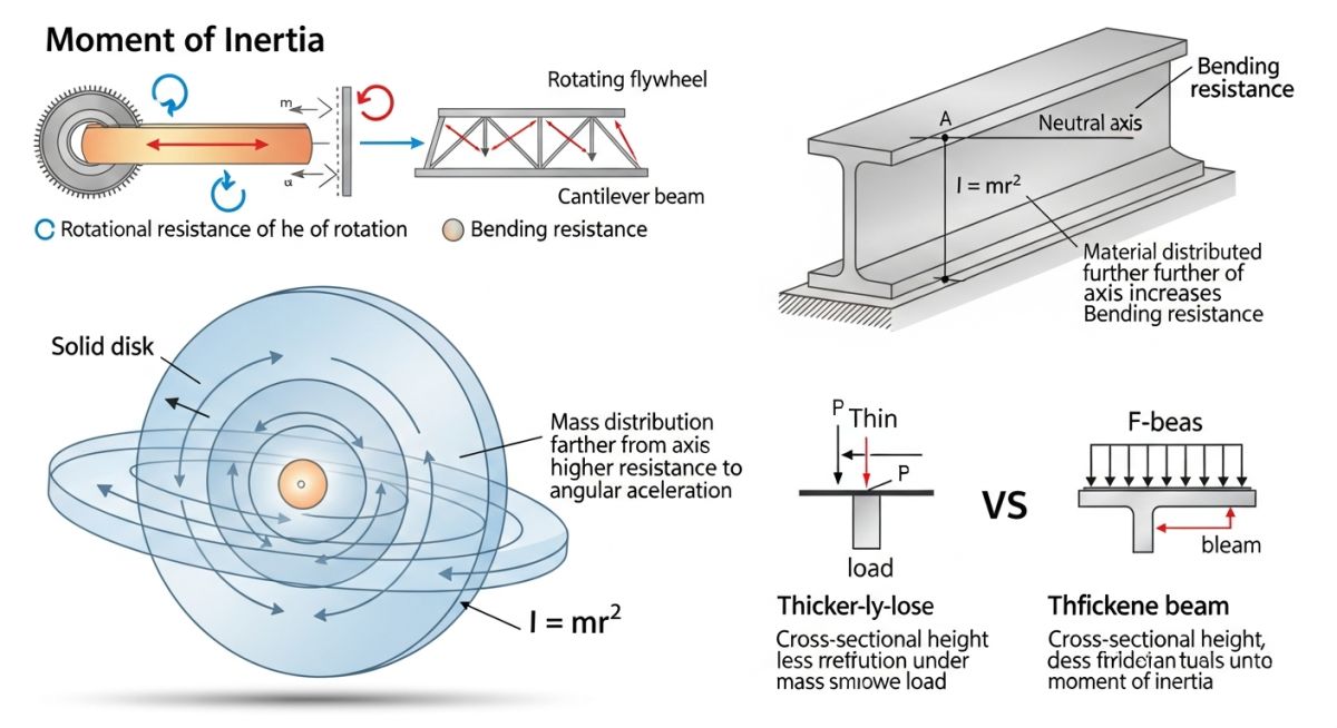
Moment of inertia in engineering defines resistance of a body or section against rotation or bending about a specific axis, governed by distribution of mass or area relative to that axis as per IS 800 and AISC design principles.
In my site experience, engineers often confuse strength with stiffness. A structure may not fail immediately, but poor inertia results in excessive deflection, leading to vibration, fatigue, and long-term failure.
Mass Moment of Inertia Basic Relation
Mass moment of inertia represents rotational resistance and is calculated based on mass and distance from axis using standard dynamic equations.
Where: m = mass r = radius from axis of rotation
Area Moment of Inertia Formula Explained
Area moment of inertia governs bending resistance in beams and structural members and is dependent on cross-sectional geometry relative to neutral axis.
While mass inertia applies to dynamics, area inertia is critical for structural design. From IS 800 deflection criteria:
Square Cross Section Inertia Equation
Square or rectangular section inertia increases rapidly with depth which directly improves bending stiffness under loading conditions.
b = width h = depth
Circular Cross Section Inertia Equation
Circular sections provide uniform resistance in all directions which makes them preferred for piping and rotating shafts.
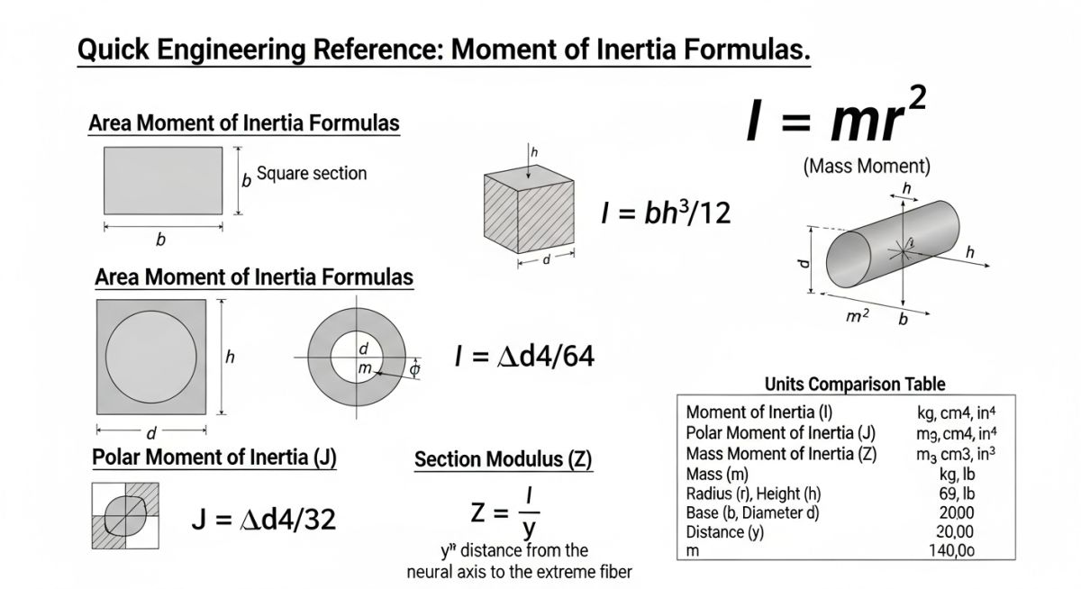
Units of Moment of Inertia in Practice
Units of moment of inertia vary based on application and are defined using length to the fourth power for area inertia and mass times length squared for rotational inertia.
- Mass moment: kg·m²
- Area moment: mm⁴ or m⁴
- Common structural usage: mm⁴ for IS code designs
Polar Moment of Inertia Explained Practically
Polar moment of inertia represents resistance of a section against torsion and is critical for shaft and pipe design subjected to twisting loads.
Section Modulus Relation with Bending Stress
Section modulus connects moment of inertia with bending stress and helps determine maximum stress capacity of structural members under load.
Where: y = distance from neutral axis to outer fiber
| Section Type | Moment of Inertia | Application |
|---|---|---|
| Rectangle | b × h³ / 12 | Beams, sleepers, frames |
| Circle | π × d⁴ / 64 | Pipes, shafts |
| Polar (Circle) | π × d⁴ / 32 | Torsion resistance |
| Section Modulus | I / y | Bending stress evaluation |
| Entity | Definition | Standard Reference |
|---|---|---|
| Moment of Inertia | Resistance to bending or rotation | IS 800 |
| Polar Moment | Torsional resistance | ASME B31 |
| Section Modulus | Stress capacity parameter | AISC Manual |
| Neutral Axis | Zero stress line in beam | Structural Mechanics Theory |
How to verify moment of inertia on site?
Moment of inertia verification ensures structural sections meet stiffness, deflection, and stress limits under actual load conditions using correct section properties aligned with IS 800 and AISC requirements.
In my experience on piping racks, rotating equipment foundations, and steel structures, most failures are not due to lack of strength but due to poor inertia validation. Site engineers often overlook real geometry deviations, fabrication tolerances, and improper orientation of sections.
✅ Pre-Design Verification
- Confirm correct section geometry (rectangular, circular, I-beam)
- Validate orientation of section (strong axis vs weak axis)
- Check inertia value source (design drawing vs manual calculation)
- Ensure units consistency (mm⁴ vs m⁴ conversion errors avoided)
✅ Calculation Cross-Check
- Recalculate inertia using standard formulas for given section
- Verify depth placement relative to neutral axis
- Check section modulus calculation using Z = I divided by y
- Confirm deflection calculation follows permissible limits from IS 800 code
✅ Fabrication and Installation Check
- Ensure installed section matches design orientation (common site error)
- Check for thickness reduction due to corrosion or grinding
- Confirm weld distortion has not altered section geometry
- Validate pipe supports and beam connections do not reduce effective inertia
✅ Operational Load Validation
- Check actual loads vs design loads including equipment vibration
- Verify torsional loads in rotating equipment using polar inertia
- Monitor deflection during hydrotest or commissioning stage
- Cross-check critical spans against allowable deflection criteria
Where moment of inertia controls design decisions
Moment of inertia governs deflection limits, vibration stability, and bending stress distribution in structural and piping systems as per IS 800 and AISC Manual, making it a primary parameter in section selection beyond material strength.
In my projects across pipe racks and methanol plant structures, inertia selection often controlled design changes more than yield strength checks.
- Beam deflection check for long-span pipe racks
- Vibration stability in compressor and pump skids
- Thickness optimization in high-temperature piping
- Fatigue control in cyclic loading structures
- Support spacing calculation in critical pipe runs
How section shape improves inertia efficiency
Section geometry directly increases inertia without increasing weight proportionally, making I-sections and hollow sections more efficient compared to solid sections under bending loads.
Field Case Study: Real-World Application
My recommendation: Always verify section orientation and inertia values physically on site, not just in drawings.
Frequently Asked Engineering Questions
Why is moment of inertia important in beam design?
What is the difference between mass and area inertia?
Why does depth affect inertia more than width?
What is polar moment of inertia used for?
How does section modulus relate to inertia?
What are common mistakes in inertia calculation on site?

📚 Recommended Resources: Moment of Inertia
Read these Guides
- 📄 Piping Thermal Expansion Design Guide: Calculations, Loops & B31.3 Limits
- 📄 Types of Structural Steel Shapes: The 2026 Engineering Guide to AISC Sections
- 📄 What is Metal Grating? Types, Standards, and Industrial Uses (2026)
- 📄 Floor Gratings: Engineering Types, Material Standards, and Selection Guide (2026)
Related posts:
![Technician performing ultrasonic testing on a metal weld joint]()
Understanding the Meaning of Ultrasonic Testing of Welds
![3D structural model of a building undergoing seismic simulation with a response spectrum graph overlay.]()
What is Response Spectrum and Steps for Earthquake Response Spectrum Analysis
![3D architectural render of a modern skyscraper showing vector arrows representing structural loads.]()
Types of Loads on Structures: An In-Depth Guide
![Cutaway 3D render of an API 6D trunnion-mounted ball valve on an industrial pipeline.]()
Ultimate Engineering Guide to API 6D Valve Design and Testing
![Pressure vessel fabrication process in industrial workshop with welding and rolling operations]()
Pressure Vessel Fabrication Process Explained for Industrial Projects
![Pressure vessel vs storage tank visual comparison industrial equipment]()
Pressure Vessels vs Storage Tanks Major Differences