How Wind Socks in Oil and Gas Protect Industrial Plants
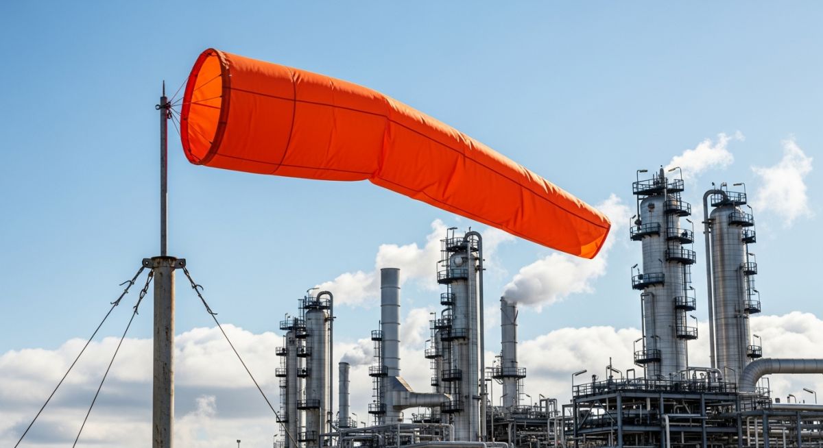
In my 20 years of managing piping systems and safety layouts across offshore platforms and onshore refineries, I have seen sophisticated gas detection systems fail due to power outages or sensor calibration drift. When a high-pressure hydrogen sulfide (H2S) line leaks, you cannot wait for a digital display to update. You look up. You look for the bright orange wind sock. It is the ultimate, fail-safe mechanical indicator that tells every operator on site exactly which way to run.
While modern plants are packed with ultrasonic detectors, infrared cameras, and telemetry, the humble wind sock remains a non-negotiable line of defense. It requires zero electrical power, operates in extreme weather, and provides instantaneous, intuitive data to personnel under extreme stress. Understanding how to select, position, and maintain these devices is a fundamental aspect of process safety management.
Key Engineering Takeaways
- Fail-Safe Design: Wind socks provide immediate wind direction data without relying on electrical power or control systems.
- Regulatory Compliance: Proper installation supports compliance with OSHA 1910.119 Process Safety Management (PSM) regulations.
- Evacuation Routing: Direct visual feedback allows personnel to escape upwind or crosswind from toxic gas plumes.
- Material Durability: High-grade polyurethane-coated nylon is required to withstand corrosive petrochemical environments.
Complete Course on
Piping Engineering
Check Now
Key Features
- 125+ Hours Content
- 500+ Recorded Lectures
- 20+ Years Exp.
- Lifetime Access
Coverage
- Codes & Standards
- Layouts & Design
- Material Eng.
- Stress Analysis
When designing the safety layout for a refinery or offshore platform, wind sock placement is not an afterthought. It requires a detailed study of local topography, prevailing wind patterns, and potential leak sources. If a wind sock is shielded by a compressor house or a major vessel, it will display turbulent eddy currents rather than the true free-stream wind direction. This can lead operators directly into a toxic gas plume during an evacuation.
Wind Speed Estimation and Aerodynamics
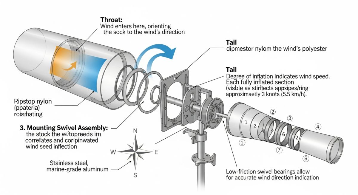
An industrial wind sock is more than a piece of fabric; it is a calibrated aerodynamic instrument. The taper of the sock determines how it responds to wind velocity. By observing the extension and angle of the wind sock, operators can estimate wind speed with surprising accuracy:
- Fully Limp (Under 3 Knots / 3.5 mph): Indicates very light, variable winds. Gas dispersion will be slow, leading to high localized concentrations of toxic gas.
- 30-Degree Angle (Approx. 6 Knots / 7 mph): The sock begins to inflate and orient. Gas plumes will drift slowly in a defined direction.
- 60-Degree Angle (Approx. 12 Knots / 14 mph): The sock is mostly inflated but still dips. Moderate dispersion of gas is occurring.
- Fully Horizontal (15 Knots / 17 mph or Higher): The sock is completely stiff and parallel to the ground. Rapid gas dispersion is occurring, but the plume will travel long distances quickly downwind.
Wind Load Calculations for Support Masts
The support mast must be engineered to withstand extreme weather, especially on offshore platforms subject to hurricane-force winds. The total wind force on the mast assembly is calculated using the standard drag equation:
Where:
F = Total wind force (pounds)
Cd = Drag coefficient (typically 1.2 for cylindrical masts, 0.5 for the wind sock basket)
q = Velocity pressure (pounds per square foot), calculated as: q = 0.00256 * V^2 (where V is the design wind speed in mph)
A = Projected area of the mast and the wind sock basket (square feet)
For a coastal facility with a design wind speed of 120 mph, the velocity pressure (q) is 36.86 psf. If the projected area of the mast and basket is 5 square feet, and we assume an average drag coefficient of 1.0, the structural support must be rated to withstand a lateral force of at least 184.3 pounds at the top of the mast. This force creates a significant bending moment at the base, requiring robust anchor bolts and structural welding.
Selecting the correct wind sock size and material is critical for ensuring long-term reliability in harsh industrial environments. The table below outlines standard sizing and material limits based on typical plant layouts.
| Throat Diameter (in) | Length (in) | Material Type | Temperature Range (C) | Best Use Case |
|---|---|---|---|---|
| 8 | 36 | Lightweight Nylon | -20 to +50 | Confined areas, low-level process skids |
| 18 | 96 | Polyurethane-Coated Nylon | -40 to +70 | Standard refinery units, tank farms |
| 36 | 144 | Heavy-Duty Vinyl Coated | -50 to +80 | Offshore platforms, high-wind coastal zones |
This matrix maps key technical entities, structural acronyms, and physical parameters to their respective industry standards.
| Entity / Acronym | Technical Definition | Physical Parameter | Standard Reference |
|---|---|---|---|
| H2S | Hydrogen Sulfide toxic gas | Density: 1.36 kg/m3 (Heavier than air) | OSHA 1910.1000 |
| API RP 754 | Process Safety Performance Indicators | Tier 1 and Tier 2 release tracking | API RP 754 |
| FAA AC 150/5345-27 | Specification for Wind Cone Assemblies | Wind speed performance (fully extended at 15 knots) | FAA AC 150/5345-27 |
A seized wind sock is worse than no wind sock at all. If the swivel bearing corrodes and locks in place, the sock will point in a single direction regardless of actual wind shifts. During an emergency, this false reading can guide personnel directly into danger. I always mandate a strict preventive maintenance schedule for all wind direction indicators.
Site Verification Checklist
-
Swivel Bearing Freedom: Verify that the wind sock frame rotates 360 degrees smoothly with minimal resistance. Test with a light breeze (under 3 knots).
-
Fabric Integrity: Inspect for UV degradation, color fading, and physical tears. Replace the sock immediately if the orange color has faded to a dull peach or if fraying is visible at the tail.
-
Illumination Check: For night operations, verify that the internal or external explosion-proof LED lights are fully functional and clean.
-
Mast Structural Integrity: Inspect the support pole, base plate, and anchor bolts for signs of corrosion or stress cracking, especially at weld joints.
-
Obstruction Audit: Ensure no new equipment, piping, or temporary structures have been installed that block the wind flow to the sock.
Field Case Study: Real-World Application
The Problem: Seized Swivel During H2S Release
At a sour gas processing facility in West Texas, a flange blowout occurred on a high-pressure H2S line. The digital gas detection system triggered alarms, but the primary wind sock was seized due to sand accumulation in the swivel bearing, pointing in the wrong direction. Operators evacuated downwind instead of upwind, leading to severe inhalation exposures and a near-fatal incident.
The Outcome: Redesigned Swivels and PM Protocols
I led the forensic engineering audit. We replaced all standard wind socks with sealed, double-ball-bearing stainless steel swivels and established a bi-monthly PM schedule. During a subsequent minor leak, the wind socks performed flawlessly, allowing 100% of the crew to evacuate safely upwind within 45 seconds.
This case highlights that safety is only as strong as its simplest mechanical link. Regular maintenance and proper material selection are critical to ensuring these devices perform when lives are on the line.
Frequently Asked Engineering Questions
What is the standard color for wind socks in oil and gas facilities?
How often should wind socks be replaced in offshore environments?
What are the mounting height requirements for industrial wind socks?
Are illuminated wind socks required for 24/7 refinery operations?
How do you calculate the wind load on a wind sock mast?
Can wind socks be used as the sole means of wind direction monitoring?
===
Complete Course on
Piping Engineering
Check Now
Key Features
- 125+ Hours Content
- 500+ Recorded Lectures
- 20+ Years Exp.
- Lifetime Access
Coverage
- Codes & Standards
- Layouts & Design
- Material Eng.
- Stress Analysis
