Table of Contents
What is Tube Bending? Working, Types, and Industrial Applications
In my 20 years of managing piping and fabrication projects, I have seen many engineers struggle with the physics of tube bending. It is not simply a matter of applying force to a piece of metal; it is a highly calculated engineering discipline. When you bend a tube, you are forcing the material to undergo simultaneous tensile and compressive stresses. The outer wall of the bend stretches and thins out, while the inner wall compresses and thickens. Managing these physical changes without causing structural failure, wrinkling, or excessive ovality is what separates a successful project from an expensive scrap pile.
Whether you are designing high-pressure hydraulic lines for an offshore platform or routing exhaust systems for automotive applications, understanding the mechanics of tube bending is fundamental. In this guide, I will share my field experience and break down the core mechanics, the primary bending methods, and the critical calculations required to achieve perfect bends every single time.
Key Takeaways from a Piping Expert
- Wall thinning and ovality must be strictly controlled to meet ASME B31.3 Process Piping requirements.
- The choice of bending method depends heavily on the tube’s wall thickness-to-diameter ratio and the required bend radius.
- Mandrels and wiper dies are necessary tools when bending thin-walled tubes to tight radii to prevent wrinkling and collapse.
- Springback is an unavoidable physical phenomenon that must be compensated for during the initial design and tooling setup.
Complete Course on
Piping Engineering
Check Now
Key Features
- 125+ Hours Content
- 500+ Recorded Lectures
- 20+ Years Exp.
- Lifetime Access
Coverage
- Codes & Standards
- Layouts & Design
- Material Eng.
- Stress Analysis
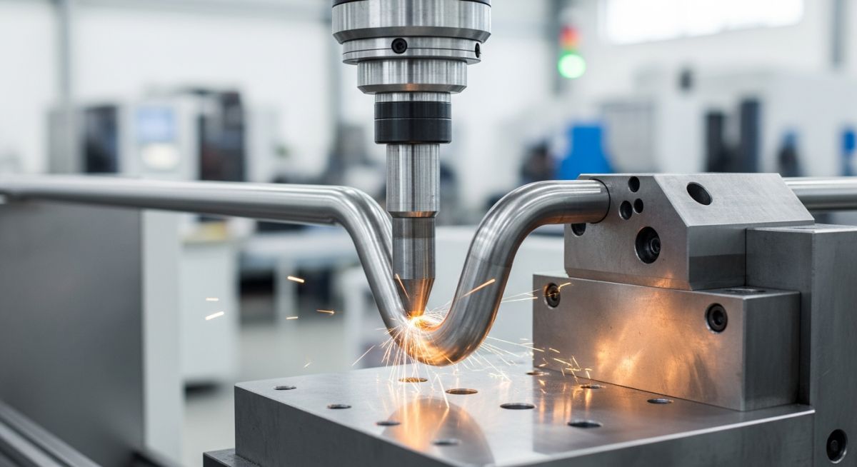
What is Tube Bending and How It Works
To understand how tube bending works, we must look at the stress distribution across the cross-section of the tube during deformation. When a bending moment is applied, the material on the outside of the bend (the extrados) is subjected to tensile stress. This causes the material to stretch, leading to wall thinning. Conversely, the material on the inside of the bend (the intrados) experiences compressive stress, which causes the wall to thicken.
Between these two zones lies the neutral axis, where the stress is theoretically zero. However, as the bend progresses, the neutral axis shifts inward toward the intrados. This shift is a critical factor in calculating the final wall thickness and structural limits of the bent tube.
Five Common Industrial Tube Bending Methods
Depending on the material, wall thickness, and bend radius, different bending methods are utilized in industrial fabrication:
- Rotary Draw Bending: The most precise method, where the tube is clamped to a rotating bend die and drawn around it. This method is ideal for tight radii and thin-walled tubes when paired with a mandrel.
- Roll Bending: Uses three adjustable rollers in a triangular configuration to produce large-radius bends, common in structural frames and coiling applications.
- Press Bending: A simple, cost-effective method where a ram with a bending die presses the tube against two counter-rollers. It is prone to causing ovality and is best suited for thick-walled tubes where aesthetics are not critical.
- Compression Bending: The tube is held stationary while a wiping shoe or roller wraps the tube around a stationary bend die. This is highly efficient for symmetrical bends.
- Stretch Bending: The tube is gripped at both ends, stretched beyond its yield point, and wrapped around a die. This minimizes springback and is widely used in the aerospace industry.
Calculating Wall Thinning and Ovality Limits
To ensure safety and compliance with standards like ASME B31.3, we must calculate the minimum wall thickness after bending. A reliable geometric estimation for wall thinning is:
Where:
• t_min = Minimum wall thickness at the extrados after bending
• t_nom = Nominal wall thickness of the straight tube
• R = Centerline bend radius
• D = Outside diameter of the tube
Ovality, or the flattening of the tube cross-section, is another critical parameter. It is calculated as:
For high-pressure applications, ASME codes typically limit ovality to a maximum of 8% for internal pressure systems, and even less for external pressure or vacuum systems to prevent collapse.
The table below outlines the typical minimum bend radius (expressed as a multiple of the outside diameter, OBD) and the allowable limits for wall thinning and ovality across common industrial materials.
| Material Specification | Min Bend Radius (OBD) | Max Wall Thinning (%) | Max Allowable Ovality (%) | Applicable Code |
|---|---|---|---|---|
| Carbon Steel (ASTM A106 Gr. B) | 1.5D (with mandrel) / 3D (without) | 12.5% | 8.0% | ASME B31.3 |
| Stainless Steel (ASTM A312 TP316L) | 1.0D (with mandrel) / 2D (without) | 15.0% | 8.0% | ASME B31.3 |
| Copper (ASTM B88 Type K) | 2.5D | 10.0% | 5.0% | ASME B31.5 |
| Titanium (ASTM B338 Gr. 2) | 3.0D (requires hot bending) | 12.0% | 6.0% | ASME B31.3 |
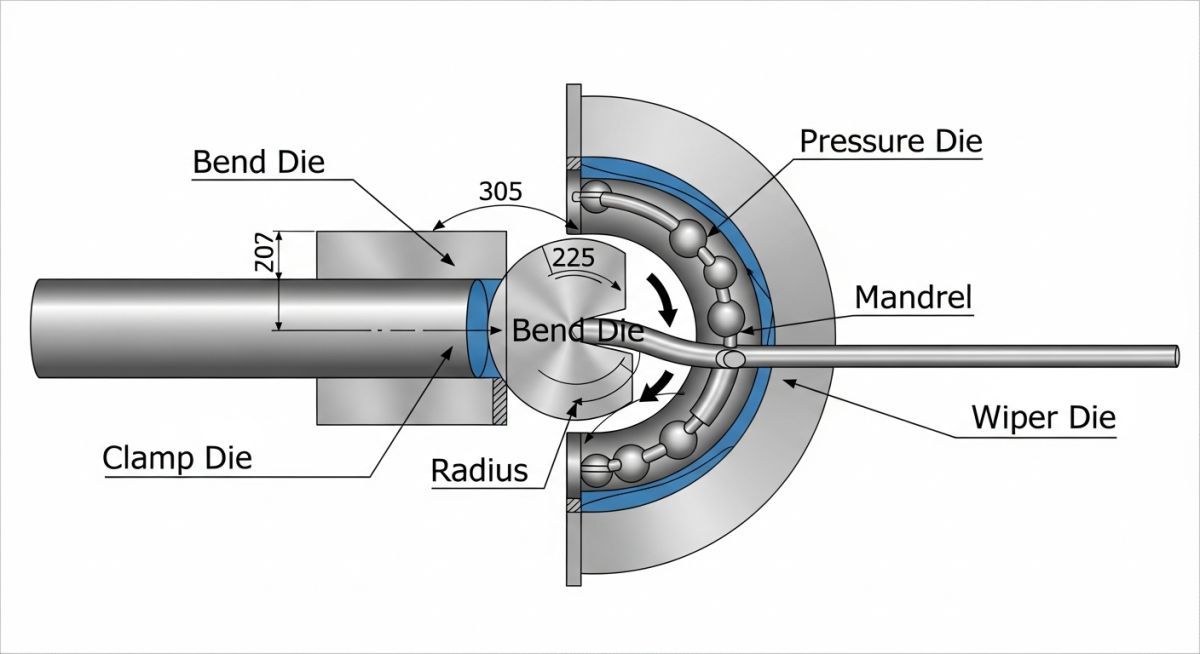
This matrix maps the primary tooling components used in rotary draw bending, their functions, and how they directly impact the quality of the finished bend.
| Tooling Component | Primary Function | Critical Parameter | Associated Code / Standard |
|---|---|---|---|
| Bend Die | Establishes the centerline radius (CLR) of the bend. | Radius tolerance (+/- 0.5mm) | ASME B16.9 / ASME B31.3 |
| Clamp Die | Secures the tube to the bend die to prevent slippage. | Clamping pressure (PSI/Bar) | ASTM A450 (General Requirements) |
| Pressure Die | Pushes the tube forward into the bend zone to reduce tension. | Boost speed matching (%) | ASME B31.1 Power Piping |
| Mandrel | Supports the inside of the tube to prevent collapse and ovality. | Shank position (mm past tangent) | ASME B31.3 Section 304.2.1 |
| Wiper Die | Prevents wrinkles from forming on the inner radius (intrados). | Rake angle and alignment | ASME B31.3 Section 304.2.1 |
How to Inspect Bent Tubes on Site
In my years on the shop floor, I have found that a structured inspection process is the only way to prevent costly field failures. Below is the exact checklist I use to verify the quality of bent tubes before they are released for installation.
Site Verification & Inspection Steps
-
Visual Inspection for Wrinkling: Check the inner radius (intrados) for any signs of wrinkling or corrugation. Wrinkles act as stress concentrators and restrict flow, violating ASME B31.3.
-
Ultrasonic Wall Thickness Measurement: Measure the wall thickness at the outermost point of the bend (extrados). Verify that the remaining wall thickness meets or exceeds the minimum design thickness calculated per code.
-
Ovality Verification: Use a vernier caliper to measure the maximum and minimum outside diameters at the center of the bend. Calculate the ovality percentage and ensure it is within the 8% limit.
-
Springback and Angle Check: Measure the final bend angle using a digital protractor. Ensure the angle is within the specified tolerance (typically +/- 0.5 degrees for precision systems).
-
Surface Crack Detection (NDT): For high-stress or cyclic service applications, perform Liquid Penetrant Testing (PT) or Magnetic Particle Testing (MT) on the extrados to check for micro-cracking.
Field Case Study: Real-World Application
The Problem: High-Pressure Hydraulic Line Failures
During the commissioning of an offshore drilling rig’s hydraulic control system, several 1.5-inch OD, 0.120-inch wall thickness ASTM A269 316L stainless steel tubes failed during pressure testing at 5,000 PSI. Visual inspection revealed severe cracking along the outer radius (extrados) of the 1.5D tight-radius bends. Ultrasonic testing showed that the wall thickness at the extrados had thinned by over 22%, dropping well below the minimum allowable thickness required by ASME B31.3.
The Solution: Tooling Optimization and Mandrel Integration
I was called in to audit the fabrication process. We discovered that the fabricator was using a standard rotary draw bender without an internal mandrel or a wiper die, relying solely on the tube’s wall strength to resist collapse. This caused extreme tensile stress on the outer wall.
We implemented a multi-ball mandrel system and a bronze-alloy wiper die. We also adjusted the pressure die boost to push the tube into the bend zone, reducing the tensile stress on the extrados. Finally, we switched to a high-viscosity synthetic lubricant to minimize friction.
The Outcome: The optimized setup reduced wall thinning from 22% to a consistent 9.5%, well within the 15% limit allowed for stainless steel. Ovality was reduced from 7.5% to 3.2%. The newly fabricated lines passed the 5,000 PSI pressure test with zero failures, saving the project over 120,000 in material and downtime costs.
Frequently Asked Engineering Questions
Common Questions About What is Tube Bending
What is the difference between pipe bending and tube bending?
How do you calculate the minimum bend radius for a tube?
What causes wrinkling on the inside of a tube bend?
When is an internal mandrel necessary during the bending process?
How does springback affect the final bend angle?
What standards govern industrial tube bending quality?

📚 Recommended Resources: Tube Bending
Read these Guides


Related posts:
![Industrial piping manifold showing different types of pipe joints including flanged and welded connections.]()
Mastering the Core Types of Pipe Joints in Industrial Piping
![Cross-section comparison of a metallurgically bonded clad pipe and a mechanically bonded lined pipe.]()
What is Cladded Pipe? Difference Between Clad and Lined Pipe
![Conceptual illustration of digital technical data exchange between an engineering office and a process equipment vendor.]()
How to Manage Technical Information Exchange With Process Equipment Vendors
![3D piping stress analysis of a Smart Tee model in START-PROF software.]()
Mastering Smart Tee Model Considerations in START-PROF Stress Analysis
![Modern industrial compressed air system installation with rotary screw compressors and receiver tanks in a clean facility.]()
Designing a Compressed Air System for Maximum Industrial Efficiency
![Coated industrial bolts on an offshore pipeline flange showing corrosion protection.]()
Coating Selection for External Bolting to Reduce Corrosion in Piping