What is a Pipeline Stopple and Why It Matters
In my 20+ years of managing high-pressure pipeline interventions, I have often faced the ultimate operational nightmare: how to repair a critical line without shutting down the entire plant or venting millions of cubic feet of product. The answer lies in a highly engineered, temporary isolation technique known as a pipeline stopple. When a simple valve bypass is not an option, stopple fittings provide a safe, reliable, and code-compliant method to isolate pressurized piping systems under full operating conditions.
Throughout my career, I have supervised numerous hot tapping and plugging operations on live hydrocarbon lines. I can tell you firsthand that executing a successful stopple operation requires a deep understanding of piping mechanics, material science, and strict adherence to safety protocols. This guide breaks down the technical details of stopple fittings, their design parameters, and how they keep modern industrial plants running smoothly during major modifications.
Key Takeaways from This Guide:
- Understand the mechanical components of a complete pipeline stopple system.
- Learn the critical design calculations for thrust force and bypass sizing.
- Discover how to maintain compliance with ASME B31.3, B31.4, and B31.8 codes.
- Identify the field verification steps necessary to prevent isolation failures.
What is a Pipeline Stopple in Piping?
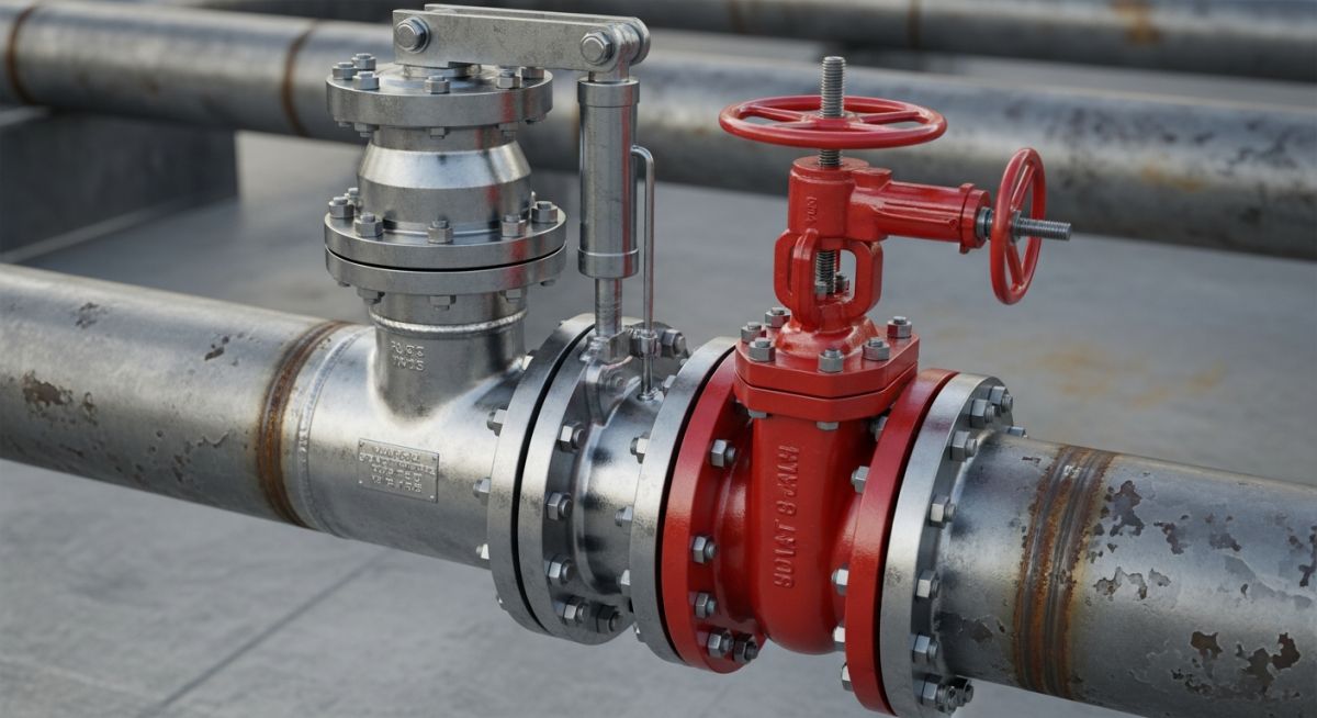
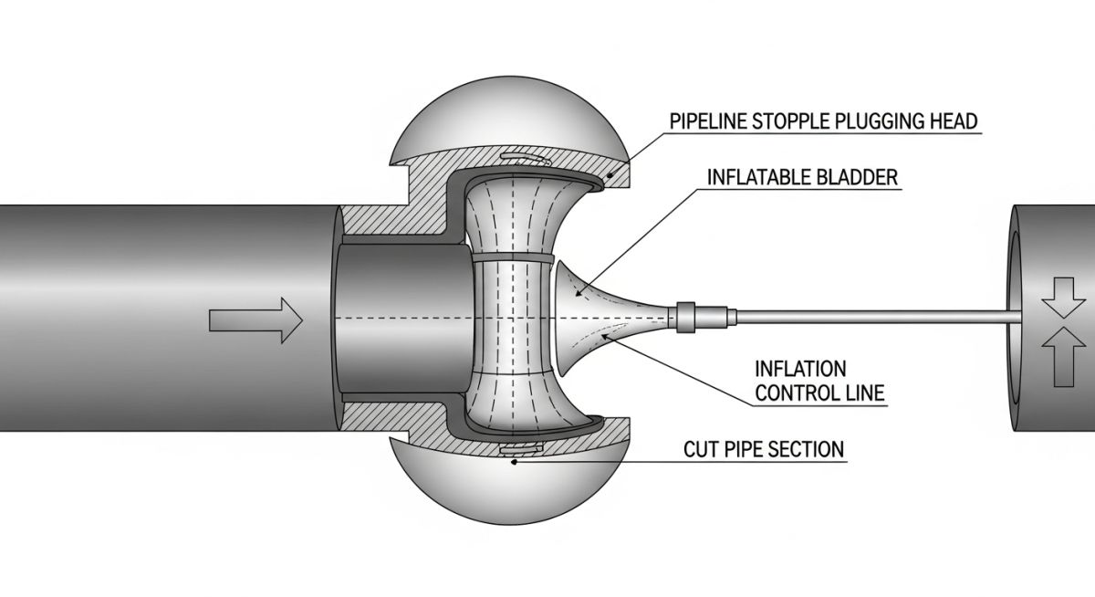
A pipeline stopple (often referred to as a line stop) is a temporary plugging system used to isolate a section of pipe for repairs, modifications, or additions. The process begins by welding a specialized split-tee fitting onto the live pipeline. A temporary sandwich valve is then mounted to the fitting, and a hot tap machine cuts a hole through the pipe wall. Once the cutter is retrieved, a stopple plugging machine is mounted on the valve. The plugging head is lowered through the valve and into the pipe, expanding to create a tight seal that blocks the flow.
To maintain downstream flow during the isolation, a bypass line is typically installed upstream of the first stopple fitting and reconnected downstream of the second stopple fitting. This double-block-and-bleed configuration ensures that maintenance crews can work safely on the depressurized section of the pipe while the rest of the system remains fully operational.
Critical Design Calculations for Stopple Operations
When designing a stopple system, we must calculate the massive thrust forces acting on the plugging head. The differential pressure across the plugging element creates a hydraulic force that tries to push the plugging head downstream. This force must be resisted by the plugging machine’s housing and the structural integrity of the split-tee fitting.
Thrust Force Calculation Formula:
Thrust Force (F) = Operating Pressure (P) x Cross-Sectional Area (A)
Where Area (A) = 3.14159 x (Internal Diameter (D) squared) / 4
Example Calculation:
Consider a 24-inch Class 600 pipeline operating at 100 bar (10 MPa) of pressure. The internal diameter of the pipe is approximately 584.2 mm (0.5842 meters).
Area (A) = 3.14159 x (0.5842 x 0.5842) / 4 = 0.268 square meters.
Thrust Force (F) = 10,000,000 Pascals x 0.268 square meters = 2,680,000 Newtons (2.68 Meganewtons or approximately 273 metric tons of force).
This calculation demonstrates why structural reinforcement and precise welding of the split-tee fitting are so important. If the fitting or the plugging machine’s control rod fails under this load, the plugging head could be blown downstream, causing catastrophic pipeline failure and severe safety hazards.
Governing Codes and Standards
All hot tapping and stopple operations must comply with strict industry standards to ensure safety and mechanical integrity. The primary codes governing these operations include:
- ASME B31.3: Process Piping, which covers piping typically found in petroleum refineries and chemical plants.
- ASME B31.4: Pipeline Transportation Systems for Liquids and Slurries.
- ASME B31.8: Gas Transmission and Distribution Piping Systems.
- API RP 2201: Safe Hot Tapping Practices in the Petroleum and Petrochemical Industries.
Selecting the correct stopple fitting requires matching the pipeline’s nominal size, wall thickness, and pressure rating. The table below outlines standard dimensions and pressure limits for typical split-tee stopple fittings across various ANSI classes.
| Nominal Pipe Size (NPS) | ANSI Class | Max Operating Pressure (psi) | Fitting Wall Thickness (in) | Bypass Size (NPS) |
|---|---|---|---|---|
| 6 inches | Class 150 | 285 psi | 0.280 in | 4 inches |
| 12 inches | Class 300 | 740 psi | 0.375 in | 8 inches |
| 24 inches | Class 600 | 1,480 psi | 0.500 in | 16 inches |
| 36 inches | Class 600 | 1,480 psi | 0.750 in | 24 inches |
Technical Mapping & Specifications Matrix
To ensure clear communication during project planning, engineers must map out the technical entities and acronyms associated with stopple operations.
| Technical Entity | Acronym | Physical Parameter | Standard Reference |
|---|---|---|---|
| Lock-O-Ring Flange | LORF | Holds the completion plug in place after stopple removal | ASME B16.5 |
| Sandwich Valve | SV | Temporary gate valve used to contain pressure during tapping | API Spec 6D |
| Plugging Head | PH | Elastomeric sealing element that blocks the pipeline bore | Manufacturer Standard |
Key Applications of a Pipeline Stopple System
Before executing any live pipeline intervention, field engineers must verify a series of critical parameters. This checklist is based on my personal field experience and is designed to prevent common mistakes that lead to seal failures or welding defects.
Pre-Operation Field Checklist
-
Ultrasonic Thickness (UT) Testing: Verify that the pipe wall thickness at the weld zone meets the minimum design requirements and is free of laminations or internal corrosion.
-
Carbon Equivalent (CE) Verification: Confirm the chemical composition of the pipeline steel to select the correct welding electrodes and preheat temperatures, preventing hydrogen-induced cracking.
-
Flow Rate and Velocity Limits: Ensure the pipeline flow velocity is within the safe range for welding (typically between 0.4 m/s and 1.5 m/s) to prevent burn-through while avoiding excessive heat sink effects.
-
Bypass Line Hydrotesting: Confirm that the temporary bypass piping has been successfully hydrotested to 1.5 times the operating pressure before opening the bypass valves.
-
Nitrogen Purge Readiness: Verify that nitrogen cylinders and purging equipment are on-site and ready to inert the isolated section before cutting or welding begins.
Field Case Study: Real-World Application
The Problem: Critical Valve Failure on a 36-Inch Crude Oil Line
During a routine inspection at a major marine terminal, a 36-inch main isolation valve was found to have a cracked gate, preventing complete shutoff. The pipeline transported 450,000 barrels of crude oil per day. Shutting down the line to replace the valve would have cost the operator an estimated 12 million per day in lost revenue and demurrage charges for waiting tankers.
The Solution: Double Stopple with a 24-Inch Bypass
Our engineering team designed a double-block-and-bleed stopple isolation system. We welded two 36-inch split-tee stopple fittings on either side of the damaged valve, along with two 24-inch bypass fittings. After hot tapping the line, we diverted the crude oil flow through the temporary 24-inch bypass. We then inserted the stopple plugging heads, isolated the damaged valve section, purged it with nitrogen, and safely replaced the valve.
The entire operation was completed in 72 hours without a single drop of oil spilled and with zero interruption to the terminal’s loading schedule. This project highlighted the immense value of using highly engineered stopple fittings for critical pipeline maintenance.
Frequently Asked Engineering Questions
What is the difference between a hot tap and a pipeline stopple?
Can a pipeline stopple be used on high-temperature steam lines?
How do you ensure a 100% bubble-tight seal with a stopple?
What are the primary materials used for stopple sealing elements?
How is the plugging head retrieved after pipeline maintenance is complete?
What safety codes govern the welding of stopple split-tees on live lines?
===FAQ_BLOCK===
Complete Course on
Piping Engineering
Check Now
Key Features
- 125+ Hours Content
- 500+ Recorded Lectures
- 20+ Years Exp.
- Lifetime Access
Coverage
- Codes & Standards
- Layouts & Design
- Material Eng.
- Stress Analysis