Table of Contents

What is an Accelerometer? Working, Selection, and Industrial Applications
In my 20 years of commissioning rotating machinery and structural monitoring systems, I have seen countless vibration issues go undetected until they caused catastrophic failures. Whether it is a high-speed centrifugal compressor in a petrochemical plant or a critical boiler feed pump, understanding the mechanical health of your assets is impossible without reliable vibration data. This is where the accelerometer becomes the most critical tool in your instrumentation arsenal.
Many young engineers treat accelerometers as simple plug-and-play black boxes. However, selecting the wrong sensor type, ignoring mounting torque, or failing to account for environmental temperatures can completely ruin your data. In this guide, I will share my field experience to help you understand how these sensors work, how to select them for harsh industrial environments, and how to avoid common installation pitfalls.
Key Engineering Takeaways:
- Learn the fundamental physics governing mass-spring-damper systems in acceleration measurement.
- Understand the core differences between IEPE, Charge Mode, and MEMS accelerometers.
- Master the selection criteria based on frequency response, sensitivity, and environmental limits.
- Implement API 670 compliant mounting techniques to ensure high-frequency signal integrity.
Complete Course on
Piping Engineering
Check Now
Key Features
- 125+ Hours Content
- 500+ Recorded Lectures
- 20+ Years Exp.
- Lifetime Access
Coverage
- Codes & Standards
- Layouts & Design
- Material Eng.
- Stress Analysis
What is an Accelerometer and How It Works
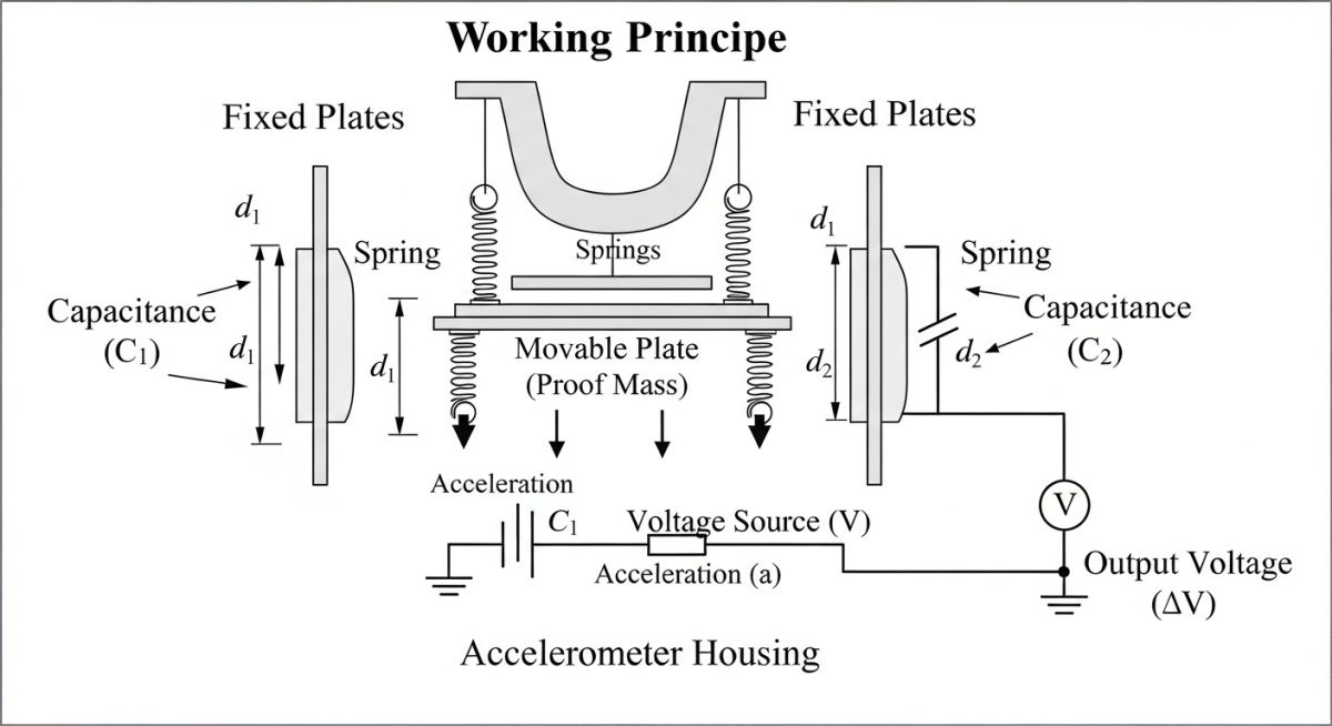
To truly understand how an accelerometer functions, we must look at the classic mass-spring-damper model. When the sensor housing experiences acceleration, the internal proof mass resists this change in motion due to its inertia. This resistance causes a relative displacement between the proof mass and the sensor housing.
This mechanical behavior is mathematically defined by combining Newton’s second law and Hooke’s law:
Restoring Force (F) = spring stiffness (k) * displacement (x)
Therefore: m * a = k * x
Acceleration (a) = (k / m) * x
This relationship shows that the acceleration is directly proportional to the displacement of the proof mass, provided the system operates well below its natural resonance frequency. The natural frequency of the sensor is calculated using the following formula:
In practice, we use different transduction methods to convert this physical displacement into an electrical signal. The three most common methods in industrial applications are:
- Piezoelectric: Active crystals (like quartz or ceramic) generate an electrical charge when subjected to mechanical stress from the moving proof mass. This is the standard for high-frequency industrial vibration monitoring.
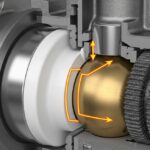
- Capacitive (MEMS): Micro-machined silicon structures where the displacement of the proof mass changes the distance between capacitive plates, altering the electrical capacitance. This is ideal for low-frequency and static acceleration measurements.
- Piezoresistive: The proof mass is attached to piezoresistive materials that change their electrical resistance when strained, making them highly suitable for shock and high-impact testing.
In my field experience, mounting an accelerometer without verifying its natural frequency can lead to severe signal saturation. If the machine’s operating frequency or its harmonics approach the sensor’s natural frequency, the output signal will amplify exponentially, causing false alarms or clipping the instrumentation amplifier. Always ensure your measurement range does not exceed 20% of the sensor’s resonant frequency.
Understanding What is an Accelerometer in Industry
In heavy industries like oil and gas, power generation, and chemical processing, accelerometers are not just diagnostic tools; they are the frontline defense against catastrophic failures. We use them to monitor critical assets such as steam turbines, gearboxes, and high-pressure pumps.
These sensors must withstand extreme conditions, including high temperatures, corrosive atmospheres, and electromagnetic interference. For this reason, industrial accelerometers are typically housed in hermetically sealed stainless steel casings and utilize double-shielded twisted-pair cabling to prevent signal degradation.
When designing a machinery protection system, we refer to standards such as API Standard 670, which defines the requirements for vibration, axial position, and bearing temperature monitoring systems. Compliance with these standards ensures that the accelerometers provide the accuracy and reliability needed to trigger automatic shutdown systems before a major mechanical failure occurs.
Selecting the correct sensor requires balancing frequency response, sensitivity, temperature limits, and physical size. The table below provides a direct comparison of the primary accelerometer types used in industrial engineering.
| Sensor Type | Frequency Range | Sensitivity Range | Temperature Limits | Primary Application |
|---|---|---|---|---|
| IEPE Piezoelectric | 0.5 Hz to 20 kHz | 10 to 500 mV/g | -50°C to 120°C | General machinery vibration, bearing diagnostics |
| Charge Mode Piezoelectric | 1 Hz to 30 kHz | 1 to 100 pC/g | -200°C to 650°C | Gas turbines, high-temperature exhaust ducts |
| Capacitive MEMS | 0 Hz (DC) to 1 kHz | 50 to 1000 mV/g | -40°C to 85°C | Structural health, low-frequency wind turbine towers |
| Piezoresistive | 0 Hz (DC) to 10 kHz | 0.1 to 10 mV/g | -40°C to 120°C | High-impact shock testing, crash safety analysis |
To ensure compliance with international standards, engineers must map physical parameters to their corresponding industry codes and design limits.
| Parameter / Entity | Acronym / Symbol | Standard Reference | Engineering Significance |
|---|---|---|---|
| Integrated Electronics Piezo-Electric | IEPE | ISA 37.2 | Standardizes internal pre-amplifier design for low-impedance voltage transmission. |
| Mechanical Vibration Evaluation | ISO 10816 | ISO 10816-3 | Defines vibration severity thresholds for industrial machines based on sensor data. |
| Transducer Electronic Data Sheet | TEDS | IEEE 1451.4 | Enables self-identification and digital calibration data storage within the sensor. |
| Mechanical Mounting of Accelerometers | ISO 5348 | ISO 5348 | Specifies physical mounting requirements to prevent high-frequency signal loss. |
Installation and Calibration Best Practices
In my years on site, I have found that over 70% of high-frequency measurement errors are caused by poor mounting. A loose sensor acts as a mechanical filter, cutting off high-frequency signals and rendering your bearing diagnostics useless. Use this checklist during your next commissioning or maintenance turnaround to guarantee accurate data.
Field Installation Verification Checklist:
-
Surface Preparation: Verify the mounting surface is machined flat to at least 1.0 micro-inch (Ra) and free of paint, rust, or debris.
-
Mounting Method: Use stud mounting for high-frequency applications (>5 kHz). Magnetic or adhesive mounts should only be used for temporary or low-frequency measurements.
-
Torque Specification: Apply the exact manufacturer-specified mounting torque (typically 18 to 30 lb-in / 2 to 3.4 Nm) using a calibrated torque wrench. Under-torquing reduces high-frequency response; over-torquing can damage the internal crystal.
-
Coupling Fluid: Apply a thin film of silicone grease or light machine oil between the sensor base and the machine surface to fill microscopic air gaps.
-
Cable Strain Relief: Secure the sensor cable within 3 to 6 inches (75 to 150 mm) of the sensor body to prevent cable whip and triboelectric noise.
-
Shielding and Grounding: Ensure the cable shield is grounded at the junction box or control system end only, preventing ground loops that introduce electrical noise.
Field Case Study: Real-World Application
The Problem: Intermittent Trips on a Boiler Feed Pump
During the commissioning of a 12 MW boiler feed pump, the plant experienced intermittent high-vibration trips. The existing velocity sensors, which were mounted via magnetic bases, showed vibration levels well within acceptable limits (under 3.0 mm/s RMS). However, the pump continued to trip on high-frequency noise, and the maintenance team could not identify the root cause. The plant was losing significant revenue due to these unscheduled shutdowns.
The Engineering Solution & Outcome
I was called to the site to troubleshoot the system. I immediately identified that the magnetic-mount velocity sensors were failing to capture high-frequency transient events due to the poor mechanical coupling of the magnet.
We replaced the temporary setup with high-temperature, stud-mounted IEPE accelerometers (100 mV/g sensitivity) directly on the pump bearing housings, in strict compliance with ISO 5348.
The new accelerometers revealed a massive vibration spike at 8.2 kHz, which was the pump’s vane-pass frequency. This high-frequency acceleration data pointed directly to impeller cavitation caused by a restricted minimum flow bypass valve. Once we adjusted the bypass valve stroke, the cavitation ceased, the high-frequency vibration dropped by 85%, and the pump operated continuously without further trips.
My Recommendation:
Never rely on magnetic-mount sensors for permanent machinery protection systems. For frequencies above 1 kHz, stud mounting is the only reliable method to ensure that high-frequency energy is accurately transmitted from the machine housing to the sensor’s internal crystal.
Frequently Asked Engineering Questions
What is the difference between an IEPE and a Charge Mode accelerometer?
How do I choose between a 10 mV/g and a 100 mV/g accelerometer?
Why is mounting torque so critical for accelerometers?
Can I use a MEMS accelerometer for high-frequency industrial vibration?
What is the purpose of TEDS in modern accelerometers?
How does temperature affect accelerometer performance?

📚 Recommended Resources: What is an Accelerometer
Related posts:
![Side-by-side 3D render of a centrifugal pump and a positive displacement gear pump showing internal components.]()
Mastering Centrifugal Pump vs Positive Displacement Pump Selection
![Industrial worker reviewing a Material Safety Data Sheet on a tablet near chemical storage.]()
What is Material Safety Data Sheet (MSDS)? | MSDS VS SDS
![Aerial view of a modern municipal wastewater treatment plant featuring circular clarifiers and aeration basins.]()
Wastewater Treatment: Process Steps, Design Considerations, and Plant Types
![An offshore crude oil drilling rig operating in the ocean at sunset.]()
Understanding Crude Oil Price and Types for Piping Design
![Steel sucker rod string being installed at an oil well pumpjack site.]()
What is a Sucker Rod? Its Types and Critical Importance
![Cutaway diagram of a fire-safe ball valve showing primary and secondary metal-to-metal seals.]()
What is Fire-Safe Valve? API 607 vs API 6FA