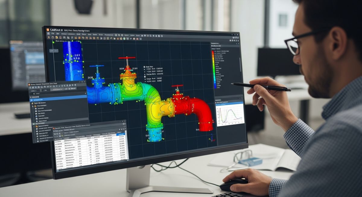
User Defined SIFs Issue: What Most Engineers Get Wrong in Stress Analysis
I still remember a shutdown incident where a perfectly designed line failed during hydrotest. The layout was clean, supports were fine, and yet the stress report showed everything within allowable limits.
But when we went deeper, the real problem surfaced — someone had overridden the code-calculated values with User Defined SIFs without verifying the basis. That single decision nearly caused a catastrophic delay in commissioning.
In my experience, User Defined SIFs are one of the most misunderstood inputs in piping stress analysis. Engineers either ignore them completely… or misuse them dangerously.
Key Takeaways
- User Defined SIFs can override ASME code values and directly impact stress results
- Wrong SIF inputs often lead to non-conservative design and hidden failure risks
- Most errors happen in tees, fabricated joints, and field welds
- CAESAR II default values are safer than incorrect manual overrides
- Every SIF override must have a traceable engineering justification
A User Defined SIF issue occurs when engineers manually override Stress Intensification Factors in piping analysis without proper justification. This can lead to inaccurate stress results, often underestimating failure risk. Correct usage requires validating against ASME B31 codes, component geometry, and fabrication type to avoid unsafe designs.
Interactive Engineering Quiz
3-question check
I use this quick test on teams before I approve any manual SIF override in a stress model.
Quiz complete
Your Score: 0 / 3
You have completed the quiz.
What is a User Defined SIF Issue in Piping Stress Analysis
In my experience, a User Defined SIF issue starts the moment someone overrides code-calculated values without fully understanding the geometry behind the fitting. A Stress Intensification Factor (SIF) represents how stress amplifies locally at discontinuities like elbows, tees, and welded joints.
Codes such as ASME B31.3 already provide standardized SIF formulas based on tested configurations. The moment you override those with a manual value, you are taking full ownership of the stress prediction accuracy.
Common Mistakes in User Defined SIFs
- Applying welding tee SIF to fabricated tee without validating reinforcement
- Using legacy project SIF values without geometry comparison
- Reducing SIF to artificially pass sustained stress checks
- Ignoring out-of-plane vs in-plane stress difference
Verification of User Defined SIFs
When I review stress models, I always ask one question: “Where did this SIF come from?”
If the answer is not supported by lab data, code clause, or manufacturer standard, I reject the model input immediately.
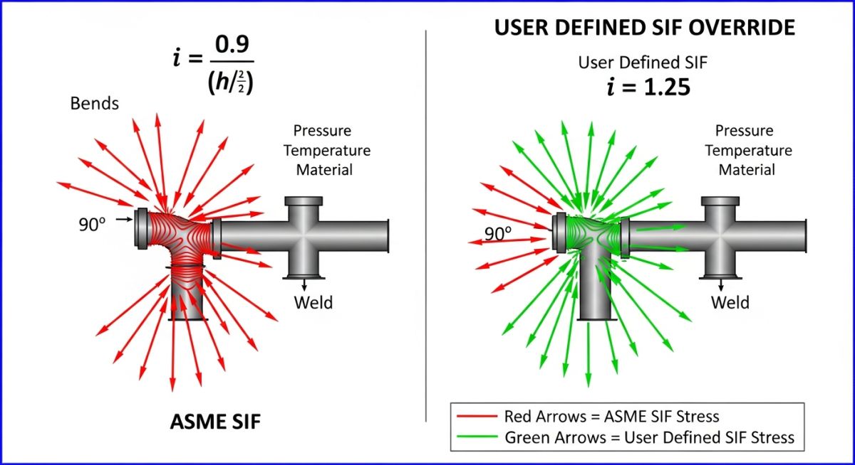
ASME vs User Defined SIF Comparison
| Criteria | ASME Code SIF | User Defined SIF |
|---|---|---|
| Source | Validated experimental data | Engineer assumption or custom study |
| Reliability | High | Depends on justification |
| Risk | Low | High if incorrect |
| Usage | Default standard | Special cases only |
Field Case Study: Real-World Application
During a refinery revamp, a 12″ branch line failed hydrotest despite stress reports showing safe results. Investigation revealed a user-defined SIF of 1.0 used for a fabricated tee.
I re-evaluated the model using ASME B31.3 equations. The correct SIF for that geometry was around 2.1. The original model had underpredicted stress by more than 40%.
We updated the CAESAR II model, rechecked load cases, and found the branch overstressed during hydrotest load combination.
• Stress increased by ~42% after correction
• Reinforcement pad added at branch
• Line successfully passed re-test without leakage
Field Lesson: Never trust a stress result if the input is wrong. A clean report can still hide a failing pipe.
Engineering FAQs: User Defined SIFs
When should I use User Defined SIF?
Is ASME SIF always safe?
Can wrong SIF cause failure?
What software uses SIF?
Are SIF and flexibility factor same?
What is biggest risk in SIF override?
Complete Course on
Piping Engineering
Check Now
Key Features
- 125+ Hours Content
- 500+ Recorded Lectures
- 20+ Years Exp.
- Lifetime Access
Coverage
- Codes & Standards
- Layouts & Design
- Material Eng.
- Stress Analysis
