Understanding the Types of Fractional Distillation Process in Refining
Over my 20 years in the piping and process engineering trenches, I have commissioned, optimized, and occasionally fought with dozens of distillation columns. Whether you are dealing with a massive atmospheric crude unit or a highly sensitive vacuum tower separating heavy gas oils, understanding the specific thermodynamic and mechanical nuances of the various types of fractional distillation process systems is what separates a highly profitable refinery from one plagued by constant off-spec product and unscheduled shutdowns.
In this guide, I will share the practical, field-tested realities of designing and operating these systems. We will bypass the overly simplified textbook explanations and dive straight into the actual hydraulic limits, thermodynamic equations, and mechanical design standards that govern these critical separation units.
Key Engineering Takeaways
- Thermodynamic selection criteria for atmospheric, vacuum, and pressure-driven fractionation.
- Rigorous calculation methods for minimum reflux ratios and actual tray requirements.
- Mechanical design considerations for column internals under varying thermal loads.
- Real-world troubleshooting strategies for tray flooding, weeping, and foaming.
- Compliance pathways for ASME Section VIII pressure vessel codes and API RP 554.
Complete Course on
Piping Engineering
Check Now
Key Features
- 125+ Hours Content
- 500+ Recorded Lectures
- 20+ Years Exp.
- Lifetime Access
Coverage
- Codes & Standards
- Layouts & Design
- Material Eng.
- Stress Analysis
Optimizing Different Types of Fractional Distillation Process Systems
To truly master the design of these systems, we must first categorize them by their operational modes and pressure regimes. The choice between atmospheric, vacuum, and pressure distillation is dictated entirely by the thermal sensitivity and relative volatility of the feed mixture.
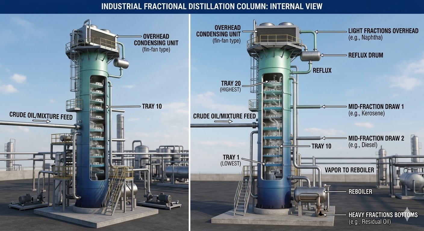
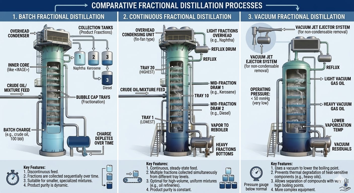
1. Atmospheric Fractional Distillation
This is the workhorse of the petroleum refinery. Operating slightly above atmospheric pressure (typically 1.2 to 1.5 bar absolute), it separates crude oil into primary fractions like naphtha, kerosene, and diesel. The design relies on a continuous temperature gradient down the column, maintained by a bottom reboiler (or direct steam injection) and an overhead reflux system.
2. Vacuum Fractional Distillation
When dealing with heavy residues that decompose or polymerize at temperatures above 350 degrees Celsius, atmospheric distillation is no longer viable. Vacuum distillation lowers the operating pressure (typically 10 to 100 mbar absolute), which significantly reduces the boiling points of the heavy hydrocarbons. This prevents thermal cracking, coking, and subsequent equipment fouling.
3. Azeotropic and Extractive Distillation
When components have extremely close boiling points or form azeotropes (where the liquid and vapor phases have identical compositions), standard fractional distillation fails. Azeotropic distillation introduces an entrainer that forms a new, lower-boiling azeotrope with one of the components, allowing it to be carried overhead. Extractive distillation uses a high-boiling solvent to alter the relative volatility of the key components without forming an azeotrope.
Core Design Calculations
Sizing a column requires determining the minimum number of theoretical stages using the Fenske equation, followed by the Underwood equations for minimum reflux ratio, and finally the Gilliland correlation for actual stages.
Fenske Equation (Minimum Stages, N_min):
N_min = ln( [x_LK / x_HK]_dist * [x_HK / x_LK]_btms ) / ln( alpha_avg )
Underwood Equations (Minimum Reflux Ratio, R_min):
Sum( (alpha_i * x_i,feed) / (alpha_i – theta) ) = 1 – q
Sum( (alpha_i * x_i,dist) / (alpha_i – theta) ) = R_min + 1
Gilliland Correlation (Actual Stages, N):
(N – N_min) / (N + 1) = 0.75 * (1 – [ (R – R_min) / (R + 1) ]^0.5668)
Where:
– x_LK, x_HK: Mole fractions of the light key and heavy key components.
– alpha_avg: Average relative volatility of the key components.
– q: Thermal state of the feed (q = 1 for saturated liquid, q = 0 for saturated vapor).
– theta: Underwood parameter (solved numerically between the volatilities of the keys).
– R: Operating reflux ratio (typically 1.2 to 1.5 times R_min).
Column Hydraulics & Flooding Limits
Once the stage count is established, we must size the column diameter to prevent flooding. Flooding occurs when the upward vapor velocity is high enough to prevent the downward flow of liquid. We calculate the flooding velocity using the Fair correlation:
Where U_f is the gas flooding velocity (m/s), C_sb is the capacity parameter (determined from tray spacing and liquid flow rates), sigma is the liquid surface tension (mN/m), and rho_L and rho_V are the liquid and vapor densities respectively. For safe operation, we design the column to operate at 75% to 85% of this flooding limit.
Parameters for Types of Fractional Distillation Process
The table below outlines the typical operating envelopes for the primary types of fractional distillation systems encountered in modern petrochemical facilities.
| Distillation Type | Pressure Range | Temperature Range | Typical Reflux Ratio | Primary Application |
|---|---|---|---|---|
| Atmospheric | 1.0 – 2.5 bar(a) | 50 – 350 °C | 1.5 – 3.0 | Crude oil primary fractionation |
| Vacuum | 10 – 100 mbar(a) | 200 – 380 °C | 0.8 – 1.5 | Heavy gas oil, lube base stocks |
| High Pressure | 5.0 – 30 bar(a) | -40 – 150 °C | 2.0 – 5.0 | Light ends recovery (C1-C4) |
| Azeotropic | 1.0 – 3.0 bar(a) | 70 – 120 °C | Variable | Ethanol dehydration |
Technical Mapping & Specifications Matrix
To ensure seamless integration between process design and mechanical piping, engineers must map physical parameters to industry standards.
| Entity / Parameter | Acronym | Design Standard | Critical Verification Metric |
|---|---|---|---|
| Pressure Vessel Shell | PVS | ASME Sec VIII Div 1 | Minimum wall thickness, wind/seismic loading |
| Column Internals | CI | API RP 554 Part 1 | Tray levelness tolerance (typically +/- 2mm) |
| Overpressure Protection | PRV | API Standard 520/521 | Relief load during total reflux failure |
| Piping Connections | PC | ASME B31.3 | Thermal expansion stress at reboiler nozzles |
Pre-Commissioning Checklist for Distillation Columns
Before introducing hydrocarbons into any fractional distillation system, a rigorous physical inspection must be completed. Below is the exact checklist I use during the final walk-down of a newly erected or turnaround column.
Mechanical & Hydraulic Verification Checkpoints
-
Tray Levelness Verification: Confirm all trays are level within +/- 2 mm across the entire diameter. Out-of-level trays cause maldistribution of liquid, leading to localized weeping and severe efficiency loss.
-
Downcomer Clearance: Measure and record downcomer clearance heights. Ensure they match the process datasheet within +/- 1.5 mm to prevent premature downcomer backup and flooding.
-
Weep Hole Inspection: Verify all tray weep holes are clear of construction debris, welding slag, and protective coatings to allow complete column draining during shutdowns.
-
Packing Bed Hold-Downs: For packed columns, verify that bed limiters and liquid distributors are securely bolted and aligned with the feed inlet nozzles.
-
Instrument Nozzle Alignment: Ensure differential pressure (DP) transmitter taps are completely clear and that the high/low pressure lines are not crossed.
Field Case Study: Real-World Application
The Problem: Severe Flooding in a Depropanizer Column
During a capacity expansion project at a major Gulf Coast refinery, a high-pressure depropanizer column experienced severe flooding whenever feed rates exceeded 78% of the new design capacity. The differential pressure across the tray section spiked rapidly, overhead propane purity dropped from 98.5% to less than 91%, and liquid carryover was detected in the overhead accumulator. The operations team suspected a foaming issue and began injecting anti-foam agents, but this yielded zero improvement.
The Diagnostic & Outcome
I was called in to analyze the column hydraulics. By reviewing the original mechanical drawings against the actual installation records, we discovered that during the turnaround, the contractor had installed standard valve trays with a 450 mm tray spacing instead of the specified high-capacity trays designed for 600 mm spacing in the flash zone.
We performed a gamma scan of the operating column, which confirmed massive liquid holdup starting at tray 14 and propagating upwards. During the next scheduled mini-turnaround, we replaced the damaged valve trays with high-capacity structured packing in the critical feed zone. This modification reduced the pressure drop by 45%, eliminated the flooding entirely, and allowed the column to operate at 105% of design capacity while maintaining 99.2% propane purity.
Direct Recommendation: Never rely solely on process simulation models when troubleshooting column hydraulics. Always cross-reference simulation outputs with physical field measurements, gamma scans, and historical mechanical drawings.
Frequently Asked Engineering Questions
What is the difference between trayed and packed fractional distillation columns?
How does reflux ratio affect the purity and energy consumption of a column?
What causes weeping in a distillation column, and how is it prevented?
Why is steam stripping used in atmospheric crude distillation?
What is the significance of the feed tray location?
How do you identify column flooding during operation?
===

📚 Recommended Resources: types of fractional distillation
Read these Guides
🎥 Watch Tutorials

Related posts:
![A mechanical sucker rod pumpjack operating in an oil field at sunset]()
What is Sucker Rod Pump System in Oil Production?
![Piping material engineer reviewing technical specifications on a tablet in an industrial plant.]()
How a Piping Material Engineer Drives Industrial Project Success
![Industrial refinery plant showing various types of static equipment]()
What is Static Equipment? Types and List of Static Equipments
![Side-by-side comparison of industrial process piping and power plant steam piping systems.]()
Differences Between ASME B31.3 and B31.1: B31.3 vs B31.1
![Large industrial steel storage tank under construction with cranes and scaffolding]()
Storage Tank Construction Method Statement: Step-by-Step Engineering Guide
![Cutaway diagram of a globe control valve highlighting the internal valve trim components]()
What is a Valve Trim? Types, Components, and Selection


