Table of Contents
What are Check Valves? Types of Check Valves & Their Symbols
In my 20-plus years of piping engineering, I have seen minor design oversights lead to catastrophic plant shutdowns. One of the most common culprits is the humble non-return valve. I remember a project in 2014 where a poorly selected swing check valve on a high-pressure pump discharge caused a water hammer so severe it tore a heavy-duty hanger clean off the structural steel. That day cemented my respect for these self-actuating components.
They do not rely on an external actuator, electrical signals, or operator intervention; they rely purely on fluid mechanics. Understanding how they operate, selecting the correct type, and interpreting their symbols is fundamental for any piping designer. Let us dive deep into the mechanics, types, and engineering standards that govern these indispensable safety devices.
- Self-Actuating Mechanism: Operates purely on differential pressure without external power.
- Diverse Configurations: Swing, lift, ball, dual-plate, and piston types serve distinct process conditions.
- Standards Compliance: Design and testing must align with API 594, API 6D, and BS 1868.
- Symbol Accuracy: Correct P&ID symbols prevent critical installation errors in the field.
Understanding How Check Valves Prevent Backflow in Piping Systems
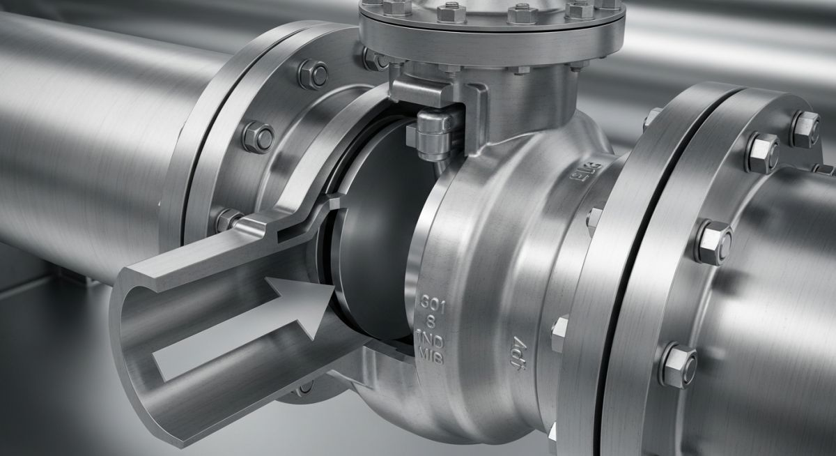
The fundamental operating principle of a check valve is simple yet elegant. It is a unidirectional valve that permits fluid to flow in one direction only. The valve opens when the upstream pressure exceeds the downstream pressure plus the mechanical resistance of the closure element (such as a spring or the weight of a disc). This minimum pressure required to open the valve is known as the cracking pressure.
The Physics of Cracking Pressure and Pressure Drop
To design a reliable system, we must calculate the cracking pressure and the subsequent pressure drop across the valve. The cracking pressure is mathematically defined as:
Once the valve is open, the pressure drop across the valve body is a function of the fluid velocity, density, and the valve’s flow coefficient (Cv). The standard pressure drop equation is:
Where the K-factor is the resistance coefficient of the specific check valve design. Swing check valves typically have a lower K-factor compared to lift check valves, making them highly efficient for low-velocity systems where pressure drop must be minimized.
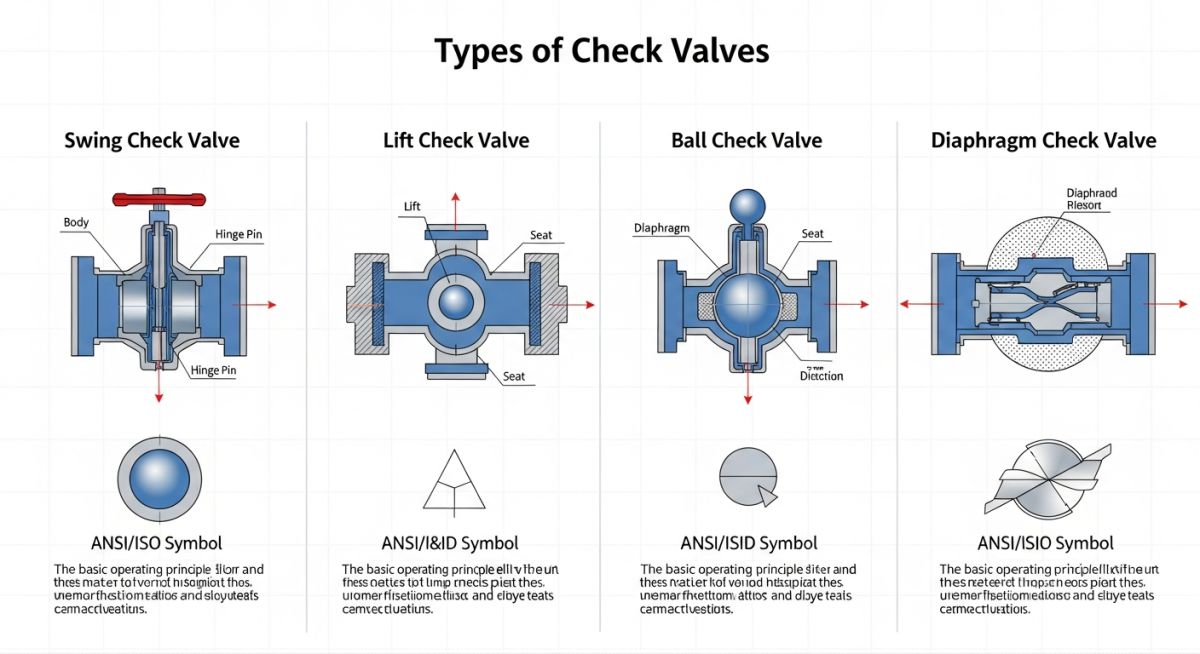
Primary Types of Check Valves
In my practice, I categorize check valves into five primary types based on their internal construction and closure mechanisms:
- Swing Check Valves: These feature a disc that swings on a hinge pin or shaft. The disc swings off the seat to allow forward flow and returns to the seat when flow ceases. They are ideal for moderate velocity lines and are typically governed by the BS 1868 standard.
- Lift Check Valves: The disc or piston lifts vertically off the seat when upstream pressure rises. They are highly suited for high-pressure, high-velocity systems, particularly in steam or gas service. They must be installed in horizontal lines unless specifically designed with a spring assist for vertical upward flow.
- Ball Check Valves: A spherical ball acts as the closure member. When flow starts, the ball is pushed upward into a guide chamber. When flow stops, gravity or backpressure seats the ball. These are excellent for viscous fluids, slurries, or wastewater applications where clogging is a concern.
- Dual-Plate Check Valves: Also known as butterfly check valves, these feature two spring-loaded plates hinged on a central pin. They offer a compact, lightweight design with a very low pressure drop and are highly effective at minimizing water hammer. They are designed in accordance with API 594.
- Piston Check Valves: Similar to lift check valves, these utilize a piston that moves within a cylinder. They often incorporate a dashpot to cushion the piston’s movement, making them ideal for pulsating flows, such as those found downstream of reciprocating compressors.
Standard swing check valves must never be installed in vertical piping runs with downward flow. In a down-flow configuration, gravity acts to keep the disc open, preventing the valve from seating quickly during backflow. This can lead to severe reverse flow, pump damage, and system failure. Always verify flow direction and piping orientation before specifying a valve model.
Water Hammer and Transient Surge Pressures
One of the most critical aspects of check valve selection is managing water hammer. When a pump trips, the fluid column decelerates and reverses. If a check valve closes too slowly, the reverse flow slams the disc shut against the seat, creating a massive pressure spike. This transient surge pressure is calculated using the Joukowsky Equation:
To prevent this, we must select fast-closing valves, such as spring-assisted dual-plate or nozzle check valves, which close before the fluid velocity can reverse and build momentum.
Selecting the correct check valve requires a balanced analysis of pressure drop, water hammer susceptibility, and installation constraints. The table below provides a comparative engineering matrix for the primary check valve types used in industrial piping systems.
| Valve Type | Relative Pressure Drop | Water Hammer Risk | Preferred Orientation | Primary Design Standard | Typical Applications |
|---|---|---|---|---|---|
| Swing Check | Low | High | Horizontal / Vertical Up | BS 1868 / API 6D | Low-velocity liquid lines, utility water |
| Lift Check | High | Medium | Horizontal Only | ASME B16.34 | High-pressure steam, air, gas lines |
| Ball Check | Medium | Medium | Horizontal / Vertical Up | API 6D / MSS SP-71 | Slurries, viscous fluids, wastewater |
| Dual-Plate | Low | Low | Horizontal / Vertical Up | API 594 | Hydrocarbon processing, large water lines |
| Piston Check | High | Low | Horizontal Only | ASME B16.34 | Pulsating flows, compressor discharge |
Technical Mapping & Specifications Matrix
The following matrix maps the core technical entities, structural acronyms, and physical parameters to their respective industry-standard references.
| Entity / Standard | Structural Acronym | Physical Parameter | Standard Reference Link |
|---|---|---|---|
| American Petroleum Institute | API | Valve Face-to-Face Dimensions | API Specification 6D |
| American Society of Mechanical Engineers | ASME | Pressure-Temperature Ratings | ASME B16.34 |
| Manufacturers Standardization Society | MSS | Quality Standard for Valve Castings | MSS SP-55 |
| British Standards Institution | BSI | Steel Check Valves for Petroleum | BS 1868 Specification |
Field Verification Checklist for Installing Check Valves Safely
In my years supervising field construction, I have found that over 70% of premature check valve failures stem from poor installation practices rather than manufacturing defects. Turbulent flow, incorrect orientation, and debris are the primary killers. Use this checklist on-site to ensure your installations are flawless.
-
Flow Direction Alignment: Verify that the flow arrow cast on the valve body matches the actual process flow direction indicated on the P&ID.
-
Piping Orientation Check: Confirm that the valve is suitable for the piping plane. Swing check valves in vertical lines must only have upward flow. Lift check valves must remain strictly horizontal unless spring-assisted.
-
Upstream Straight Run: Ensure there is a minimum of 5 to 10 nominal pipe diameters of straight, unobstructed pipe upstream of the valve to minimize turbulence and disc chatter.
-
Internal Inspection: Manually cycle the disc, ball, or piston before installation to verify smooth, unhindered movement. Check for protective shipping blocks or grease that must be removed.
-
Flange Bolt Torque: Tighten flange bolts in a star pattern to the torque values specified in the piping specification, preventing body distortion that could bind the internal hinge mechanism.
Field Case Study: Real-World Application
At a combined-cycle power plant, the high-pressure boiler feed pumps experienced severe piping vibration and a loud, metallic banging sound every time a pump tripped. The system utilized standard 12-inch swing check valves designed to BS 1868. Transient hydraulic modeling revealed that during a pump trip, the fluid column decelerated rapidly. The slow-closing swing disc allowed a reverse flow velocity of 2.4 meters per second to establish before slamming shut, generating transient surge pressures exceeding 45 bar above the normal operating pressure. This threatened the integrity of the multi-stage pumps and nearby piping welds.
I led the engineering team to resolve this issue. We replaced the slow-closing swing check valves with spring-assisted, axial-flow nozzle check valves designed to API 594. Because of the short stroke length and spring-assisted closure, the nozzle check valve closed in less than 0.15 seconds—well before the fluid column could reverse direction. Upon commissioning, the transient surge pressure spike dropped from 45 bar to less than 2.5 bar. The audible banging was completely eliminated, and vibration levels on the discharge piping returned to safe, baseline limits.
My direct recommendation for high-energy, fast-decelerating systems is to avoid standard swing check valves entirely. Instead, perform a transient surge analysis during the FEED stage and specify axial nozzle check valves to protect your critical rotating equipment.
Frequently Asked Engineering Questions
What is the difference between a swing check valve and a lift check valve?
Why is cracking pressure important when selecting a check valve?
Can check valves be installed in vertical piping runs?
What causes a check valve to slam, and how can it be prevented?
How does API 594 differ from API 6D for check valves?
What is the purpose of a bypass line around a check valve?
===FAQ_BLOCK===
Complete Course on
Piping Engineering
Check Now
Key Features
- 125+ Hours Content
- 500+ Recorded Lectures
- 20+ Years Exp.
- Lifetime Access
Coverage
- Codes & Standards
- Layouts & Design
- Material Eng.
- Stress Analysis

📚 Recommended Resources: check valves
Read these Guides
🎓 Advanced Training


Related posts:
![Professional land surveyor using a total station for a topographic survey in an open field]()
Understanding Land Mapping and the True Topographic Survey Cost
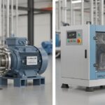
![Side-by-side comparison of an industrial centrifugal pump and a rotary screw compressor.]()
What is the Difference Between Pump and Compressor Systems?
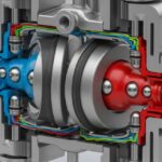
![Cutaway 3D render of an industrial air-operated double-diaphragm pump showing internal components.]()
Understanding Diaphragm Pumps: A Comprehensive Guide for Industrial Plants
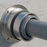
![A metallic pipe sleeve embedded in a concrete wall with a carrier pipe passing through it.]()
What is a Pipe Sleeve and How Does It Protect Piping?
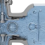
![Cross-section diagram of a control valve showing cavitation bubbles and flashing liquid.]()
How to Prevent Control Valve Cavitation and Flashing Damage
![Side-by-side comparison of ASME Section VIII Division 1 and Division 2 pressure vessels with technical blueprints.]()
Understanding the Difference Between ASME Sec VIII Div 1 vs Div 2