Table of Contents

What is Sucker Rod Pump System in Oil Production?
In my 20 years of managing upstream piping and production systems, I have walked through countless oil fields where the horizon is dominated by the rhythmic nodding of pumpjacks. These mechanical workhorses, technically known as sucker rod pump systems or beam pumps, are the backbone of global artificial lift operations. When reservoir pressure declines to a point where a well can no longer flow naturally, we must introduce mechanical energy to lift the crude to the surface.
Understanding the intricate mechanics of these systems is not just an academic exercise; it is a fundamental requirement for maximizing well run-life and minimizing costly workover operations. From the surface prime mover down to the traveling valve thousands of feet below ground, every component must operate in perfect harmony. Let us explore the engineering principles, design calculations, and field realities that govern these indispensable systems.
Key Engineering Takeaways
- Understand the critical role of the downhole positive displacement pump in artificial lift.
- Learn how to calculate peak polished rod loads to prevent mechanical fatigue.
- Identify the primary differences between API rod grades and their specific service environments.
- Discover field-proven strategies to mitigate fluid pound and gas interference.
- Master the inspection protocols required to maintain system integrity under API RP 11G.
How Does a Sucker Rod Pump Operate?
The operation of a sucker rod pump relies on a beautifully simple mechanical sequence. The prime mover, which can be an electric motor or an internal combustion engine, provides high-speed rotational energy. This energy is transmitted via v-belts to a gear reducer, which reduces the speed and multiplies the torque. The low-speed shaft of the gear reducer drives the crank arm, converting pure rotation into a reciprocating motion via the pitman arms and the walking beam.
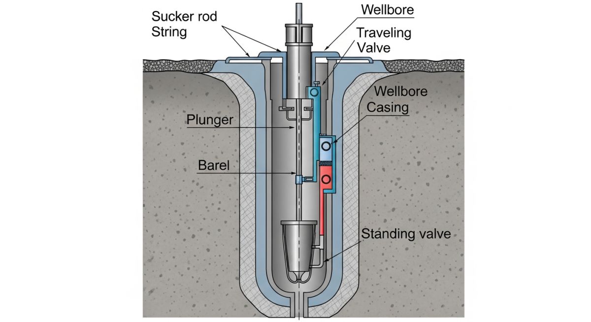
At the wellhead, the horsehead and bridle assembly ensure that the polished rod moves in a strictly vertical path. This vertical reciprocating motion is transmitted down the wellbore through the sucker rod string to the downhole pump. The downhole pump itself is a positive displacement plunger pump consisting of two key valves: the standing valve, which is fixed at the base of the pump, and the traveling valve, which is attached to the moving plunger.
The Pumping Cycle: Upstroke and Downstroke
During the upstroke, the plunger moves upward. This motion causes the traveling valve to close under the weight of the fluid column above it, lifting the fluid toward the surface. Simultaneously, a low-pressure zone is created below the plunger, which causes the standing valve to open, allowing new reservoir fluid to enter the pump barrel.
During the downstroke, the plunger moves downward. The standing valve closes under the hydrostatic pressure of the fluid in the wellbore, preventing fluid from flowing back into the formation. The traveling valve opens, allowing the fluid trapped in the pump barrel to pass through the plunger into the tubing string above, ready to be lifted on the next upstroke.
Critical Design Calculations
To design a reliable system, we must calculate the mechanical loads acting on the polished rod. The Peak Polished Rod Load (PPRL) and Minimum Polished Rod Load (MPRL) are calculated using the following engineering formulas:
MPRL = Wr * [1 – (S * N^2) / 70500] – 0.127 * Wf
Where:
Wr = Weight of the sucker rod string in the well fluid (pounds)
Wf = Weight of the fluid column above the plunger (pounds)
S = Polished rod stroke length (inches)
N = Pumping speed (strokes per minute)
The term (S * N^2) / 70500 represents the acceleration factor, which accounts for the dynamic forces introduced by the reciprocating motion.
In my experience, neglecting these dynamic forces in deep wells (greater than 6,000 feet) is a recipe for disaster. The elastic behavior of the long rod string causes it to stretch and contract, which can significantly increase the actual peak loads beyond static calculations. Engineers must utilize specialized software based on the wave equation, as outlined in API RP 11L, to accurately model these downhole dynamics.
What Are Sucker Rod Pump Specifications?
Selecting the correct rod material and grade is paramount to preventing premature fatigue failures. Sucker rods are subjected to cyclic tensile loading, making them highly susceptible to fatigue, especially in corrosive environments containing hydrogen sulfide (H2S) or carbon dioxide (CO2).
| API Grade | Minimum Tensile Strength (psi) | Yield Strength (psi) | Recommended Service Environment |
|---|---|---|---|
| Grade C | 90,000 – 115,000 | 60,000 | Non-corrosive or chemically treated light-to-medium loads. |
| Grade K | 85,000 – 115,000 | 55,000 | Highly corrosive (H2S and CO2) environments with light-to-medium loads. |
| Grade D | 115,000 – 140,000 | 85,000 | Heavy loads in non-corrosive or effectively inhibited wells. |
| High-Strength (Special Alloys) | Up to 150,000 | 115,000 | Ultra-deep wells with heavy loads; requires strict corrosion inhibition. |
To ensure seamless integration of surface and downhole components, engineers must map out the entire system architecture. The table below outlines the critical interfaces, design standards, and primary failure modes of each major component.
| Component | API Standard | Primary Function | Critical Failure Mode | Mitigation Strategy |
|---|---|---|---|---|
| Prime Mover | API Spec 11E | Provides rotational energy | Overheating / Phase imbalance | Soft starters, VSD integration |
| Gear Reducer | API Spec 11E | Reduces speed, multiplies torque | Gear tooth wear / Lubrication failure | Regular oil analysis, correct viscosity |
| Polished Rod | API Spec 11B | Seals wellhead, transfers load | Surface scoring / Packing wear | Proper alignment, packing lubrication |
| Sucker Rod String | API Spec 11B | Transmits reciprocating motion | Fatigue parting / Thread galling | Correct makeup torque, corrosion inhibitors |
| Downhole Pump | API Spec 11AX | Displaces fluid to surface | Valve pitting / Plunger abrasion | Hardened materials, sand screens |
How to Inspect Sucker Rod Pump Installations?
A structured inspection routine is the most effective defense against catastrophic mechanical failures. In my experience, over 70% of premature rod failures can be traced back to improper installation torque or minor surface damage that acts as a stress concentration point. Use this field checklist during routine maintenance and well workovers.
Pre-Commissioning & Maintenance Checklist
-
Polished Rod Alignment: Verify that the polished rod is perfectly centered over the stuffing box throughout the entire stroke. Misalignment causes severe packing wear and localized bending stresses.
-
Gearbox Lubrication: Check the oil level and inspect for water contamination or metal shavings. Ensure the lubricant viscosity matches the ambient temperature requirements specified in API Spec 11E.
-
Counterbalance Verification: Perform a crank balance test. An unbalanced unit places excessive torque loads on the gear reducer, leading to premature gear tooth pitting.
-
Sucker Rod Thread Inspection: During rod makeup, ensure threads are thoroughly cleaned and inspected for galling. Apply the correct API-recommended makeup torque using calibrated power tongs.
-
Dynamometer Testing: Run a baseline dynamometer test immediately after startup. This provides a “heart monitor” reading of the downhole pump, identifying fluid pound, gas lock, or tubing leaks.
-
Chemical Injection Rates: Verify that corrosion inhibitors and scale preventatives are being injected at the calculated parts-per-million (ppm) ratio to protect the downhole metallurgy.
Field Case Study: Real-World Application
The Problem: Chronic Rod Parting in the Permian Basin
An operator in the Permian Basin was experiencing severe operational headaches with an 8,200-foot well. The well was equipped with a standard API Grade D sucker rod string. Every 90 to 120 days, the rod string would part in the middle section, requiring an expensive workover rig to pull the tubing and fish the broken rods.
Fluid analysis revealed high concentrations of hydrogen sulfide (H2S) and carbon dioxide (CO2). Furthermore, the well was experiencing severe fluid pound due to declining reservoir pressure, which subjected the rod string to violent compressive shock loads on every downstroke.
The Solution & Engineering Outcome
As the lead consultant, I recommended a complete system redesign. First, we replaced the uniform Grade D rod string with a tapered design. We utilized high-strength, corrosion-resistant API Grade K rods in the upper and middle sections to handle the tensile loads and resist H2S embrittlement. In the lower section, we installed heavy sinker bars to keep the rod string in tension during the downstroke, eliminating the buckling that led to fatigue.
Second, we integrated a Variable Speed Drive (VSD) on the surface motor. By programming the VSD to slow down the pumping speed during the downstroke, we successfully mitigated the fluid pound. Finally, we optimized the continuous chemical injection program to ensure a protective film of corrosion inhibitor coated the entire rod string.
The results were outstanding. The well’s run-life extended from an average of 105 days to over 780 days without a single rod failure, reducing operating expenses by over 180,000 annually.
This case highlights a fundamental truth in petroleum engineering: you cannot solve a downhole mechanical problem by simply throwing stronger materials at it. You must analyze the chemical environment, the fluid dynamics, and the mechanical stresses as a single, integrated system.
Frequently Asked Engineering Questions
What is the difference between a sucker rod pump and a beam pump?
How do you prevent gas lock in a sucker rod pump?
What causes a sucker rod string to part?
How does a dynamometer card help in troubleshooting?
What is the maximum depth for a sucker rod pump?
How do you select the correct sucker rod grade?
===
Complete Course on
Piping Engineering
Check Now
Key Features
- 125+ Hours Content
- 500+ Recorded Lectures
- 20+ Years Exp.
- Lifetime Access
Coverage
- Codes & Standards
- Layouts & Design
- Material Eng.
- Stress Analysis

Related posts:
![Piping material engineer reviewing technical specifications on a tablet in an industrial plant.]()
How a Piping Material Engineer Drives Industrial Project Success
![Industrial refinery plant showing various types of static equipment]()
What is Static Equipment? Types and List of Static Equipments
![Side-by-side comparison of industrial process piping and power plant steam piping systems.]()
Differences Between ASME B31.3 and B31.1: B31.3 vs B31.1
![Large industrial steel storage tank under construction with cranes and scaffolding]()
Storage Tank Construction Method Statement: Step-by-Step Engineering Guide
![Cutaway diagram of a globe control valve highlighting the internal valve trim components]()
What is a Valve Trim? Types, Components, and Selection
![Towering steel cold box structure at an industrial cryogenic air separation unit.]()
What is a Cold Box in Cryogenic Plant Systems?