Table of Contents
Mastering Smart Tee Model Considerations in START-PROF Stress Analysis
In my 20-plus years of piping stress analysis, I have seen countless projects suffer from over-designed piping loops, unnecessary spring hangers, and inflated structural costs. Why does this happen? Because traditional stress analysis software packages often treat branch connections as simple, zero-dimensional points with static, overly conservative Stress Intensification Factors (SIFs). When PASS/START-PROF introduced its Smart Tee Model, it completely changed how we approach piping intersections. Instead of relying on outdated, simplified assumptions, this model dynamically evaluates the intersection as a complex, three-dimensional assembly of shell and beam elements.
When you configure a branch connection using traditional methods, you are often forced to manually calculate SIFs or accept the default code values, which frequently overestimate the localized stresses. In my experience, using the Smart Tee model allows us to capture the true physical behavior of the piping intersection. This results in more realistic stress distributions, lower calculated nozzle loads, and significant savings in material and fabrication costs.
Key Engineering Takeaways
- Understand the geometric limits of ASME B31J before applying the model.
- Correctly define the branch-to-run thickness ratio to avoid localized stress errors.
- Avoid double-accounting for flexibility factors when combining manual SIFs with software defaults.
- Verify weld profiles and reinforcement pad dimensions against actual field fabrication drawings.
- Use the Smart Tee model to eliminate unnecessary expansion loops in high-temperature systems.
Complete Course on
Piping Engineering
Check Now
Key Features
- 125+ Hours Content
- 500+ Recorded Lectures
- 20+ Years Exp.
- Lifetime Access
Coverage
- Codes & Standards
- Layouts & Design
- Material Eng.
- Stress Analysis
Why Use Smart Tee Model considerations in START-PROF?
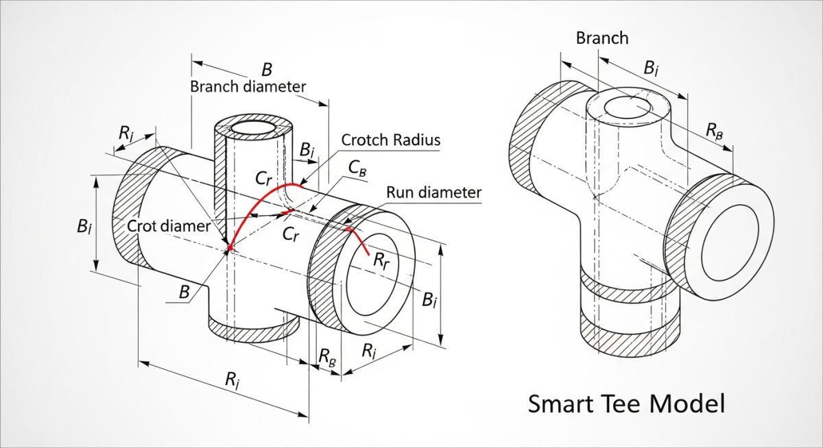
Traditional piping codes like ASME B31.3 historically relied on simplified, empirical formulas to determine SIFs. These formulas assume that the branch connection is a single point in space. However, in reality, a tee is a highly complex three-dimensional structure. The run pipe deforms ovally under bending moments, and the branch pipe experiences localized warping at the intersection.
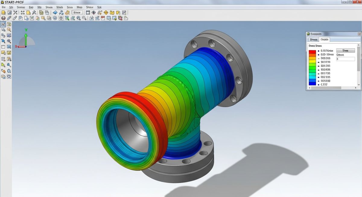
The Smart Tee model in PASS/START-PROF addresses this by utilizing the latest ASME B31J standard data. Instead of a single node, the software automatically generates a sub-model consisting of multiple nodes and virtual rigid or flexible elements. This sub-model accurately represents the physical volume of the tee, the flexibility of the run pipe wall, and the stress concentration at the crotch of the branch.
Mathematical Foundations of the Smart Tee Model
To understand how the Smart Tee model works, we must look at how flexibility factors and stress intensification factors are calculated. In traditional B31.3 calculations, the stress intensification factor is calculated as zero point nine divided by the characteristic header thickness parameter raised to the power of two thirds. This simplified calculation does not account for the actual thickness of the branch pipe or the presence of a reinforcement pad.
Under the ASME B31J methodology implemented within the Smart Tee model, the software calculates separate flexibility factors for the run and branch sides. The flexibility factor for the branch connection under out-of-plane bending is determined by a complex function of the diameter-to-thickness ratio of the run pipe and the branch-to-run diameter ratio. By calculating these factors dynamically, START-PROF provides a much more accurate representation of the system’s overall stiffness.
Do not blindly apply the Smart Tee model to all branch connections. If your branch-to-run diameter ratio is less than zero point one or greater than one point zero, the ASME B31J equations reach their mathematical limits. In these scenarios, PASS/START-PROF will generate a warning. Ignoring this warning can lead to highly inaccurate stress results, potentially underestimating the localized stresses at the crotch of the tee.
In my experience, when dealing with large-diameter, thin-walled piping systems, the difference between traditional B31.3 calculations and the Smart Tee model can be night and day. Traditional calculations often show the system failing due to overstress at the branch, forcing the engineer to add expensive expansion loops. The Smart Tee model, by accounting for the local flexibility of the run pipe wall, often shows that the stresses are well within acceptable limits, saving significant project costs.
The table below outlines the strict geometric limits defined by ASME B31J for the valid application of the Smart Tee model in PASS/START-PROF. Operating outside these limits requires alternative finite element analysis methods.
| Geometric Parameter | Minimum Limit | Maximum Limit | Code Reference |
|---|---|---|---|
| Branch-to-Run Diameter Ratio (d/D) | 0.10 | 1.00 | ASME B31J Table 1-1 |
| Run Diameter-to-Thickness Ratio (D/T) | 10.00 | 100.00 | ASME B31J Table 1-1 |
| Branch-to-Run Thickness Ratio (t/T) | 0.05 | 2.00 | ASME B31J Table 1-1 |
| Reinforcement Pad Thickness Ratio (Te/T) | 0.00 (No Pad) | 1.50 | ASME B31J Section 3.2 |
This matrix maps the core technical entities, structural acronyms, and physical parameters utilized during the configuration of the Smart Tee model in PASS/START-PROF.
| Entity / Acronym | Physical Parameter | START-PROF Input Field | Standard Reference |
|---|---|---|---|
| SIF (Stress Intensification Factor) | Fatigue strength reduction factor | Calculated Automatically | ASME B31J |
| Flexibility Factor (k-factor) | Rotational stiffness modifier | Calculated Automatically | ASME B31.3 Appendix D |
| Repad (Reinforcement Pad) | Width and thickness of pad | Pad Width / Pad Thickness | ASME B31.3 Paragraph 328.5.4 |
| Weld Leg Length (tc) | Fillet weld size at crotch | Weld Leg Size | ASME B31.3 Figure 328.5.4D |
How to Verify Smart Tee Inputs?
Before running your stress analysis, you must verify that the input parameters in PASS/START-PROF match the physical reality of the piping system. A single incorrect input can lead to highly inaccurate stress results. Use the checklist below to verify your model.
Site Verification Checkpoints
-
Verify Run and Branch Wall Thicknesses: Ensure that the nominal wall thicknesses entered in PASS/START-PROF match the actual pipe schedules specified on the piping isometric drawings. Do not forget to account for mill tolerance.
-
Confirm Reinforcement Pad Dimensions: If a reinforcement pad is used, verify that the pad width and thickness match the piping specifications. Incorrect pad dimensions will lead to inaccurate SIF calculations.
-
Check Weld Leg Lengths: Ensure that the weld leg lengths entered in the software match the minimum requirements specified in ASME B31.3 Figure 328.5.4D.
-
Validate Material Properties: Double-check that the material properties, including the elastic modulus and thermal expansion coefficient, are correct for the design temperature.
-
Review Boundary Conditions: Ensure that the supports and anchors surrounding the branch connection are modeled correctly. Over-constraining the system can lead to artificial stress concentrations at the tee.
Field Case Study: Real-World Application
During the design of a high-pressure steam line for a power plant, a 24-inch by 12-inch branch connection was failing stress analysis under thermal expansion cases. Traditional stress analysis software, using standard ASME B31.3 Appendix D formulas, calculated a stress ratio of 142% at the branch crotch. To resolve this, the design team proposed adding a massive 3D expansion loop, which would require an additional 45,000 in piping materials, structural steel supports, and fabrication labor.
I was brought in to review the design. Instead of accepting the conservative traditional results, I remodeled the intersection in PASS/START-PROF using the Smart Tee model based on ASME B31J. By accounting for the local flexibility of the 24-inch run pipe wall, the software calculated a realistic flexibility factor that allowed the branch to absorb thermal expansion. The calculated stress ratio dropped from 142% to 78%, completely eliminating the need for the expansion loop and saving the project 45,000.
This case study highlights the immense value of using advanced modeling techniques. By moving away from overly conservative, simplified formulas and embracing the physical accuracy of the Smart Tee model, we can design safer, more cost-effective piping systems.
Frequently Asked Engineering Questions
Applying Smart Tee Model considerations in START-PROF Safely
What is the primary difference between traditional SIFs and the Smart Tee model?
Can I use the Smart Tee model for reinforced branch connections?
What happens if my branch-to-run diameter ratio is outside the ASME B31J limits?
Does the Smart Tee model account for pressure elongation effects?
How does the Smart Tee model affect nozzle load calculations?
Is the Smart Tee model compliant with ASME B31.1 (Power Piping)?
===FAQ_BLOCK===

Related posts:
![Outdoor pipeline block valve station with large isolation valves and actuators.]()
What are Pipeline Block Valves and How to Design Stations
![3D CAD model of an industrial process plant showing equipment clearances and access platforms.]()
A Guide to Plant Clearances and Access Requirements
![Engineering technical bid evaluation spreadsheet comparing vendor specifications and compliance metrics.]()
How to Master Technical Bid Evaluation for Complex Engineering Procurement
![Large-diameter steel pipes with protective blue anti-corrosive epoxy coating stacked in an industrial facility.]()
Protecting Steel Pipes with Anti-Corrosive Steel Pipe Coatings
![3D CAD model of industrial piping showing stress intensification factor heatmaps at elbows and tees.]()
Why Stress Intensification Factor in Piping Dictates Fatigue Life
![A collection of different industrial pipe flange gaskets on a workbench]()
How to Select the Best Pipe Flange Gaskets for Piping Systems