
Spring Hanger Pipe Support Selection Procedure for Piping Stress Analysis
In my 20-plus years of executing piping stress analysis for high-temperature petrochemical plants, I have seen countless piping systems suffer from catastrophic support failures. Most of these failures do not stem from complex transient events; they happen because an engineer rushed through the spring hanger selection process. When a pipe heats up, it expands. If you anchor it rigidly, the thermal expansion forces will crack your pump nozzles, buckle your structural steel, or rupture the pipe wall itself. That is where spring hangers come in. They provide a flexible supporting force that accommodates vertical thermal movement while maintaining system equilibrium.
In this guide, I will walk you through the exact step-by-step spring hanger selection procedure that I use on major industrial projects. We will cover the core physics, the mathematical calculations for load variability, and how to model these components accurately in CAESAR II. If you want to design systems that stand the test of time and pass rigorous code audits, you must master these fundamentals.
What You Will Learn in This Guide
- The mathematical formula for calculating spring variability and why the 25% limit is a hard boundary in piping design.
- How to choose between variable spring hangers and constant effort supports based on thermal travel.
- Step-by-step workflow for extracting operating and cold loads from CAESAR II stress models.
- Field verification techniques to ensure the physical spring matches your analytical design.
How to Master Spring Hanger Pipe Support Selection
Spring Hanger Selection Criteria: The engineering rules governing the choice between variable and constant spring supports based on thermal movement limits and load variability thresholds defined by ASME B31.3.
To select the correct spring hanger, we must first understand the fundamental difference between variable spring hangers and constant spring hangers. A variable spring hanger uses a helical coil spring where the supporting force changes as the spring compresses or extends. This change in force is directly proportional to the spring rate (stiffness) and the thermal displacement of the pipe.
The governing equation for a variable spring is:
Because the force varies, the piping system experiences a different supporting force in its cold (ambient) state versus its hot (operating) state. This difference in force is transferred back into the piping system as an unbalanced load, which must be absorbed by adjacent rigid supports or equipment nozzles. To prevent excessive load transfer, ASME B31.3 and MSS SP-58 enforce a strict limit on load variability.
The Load Variability Formula
In my practice, the very first calculation I perform after running a preliminary stress analysis is the variability check. The formula is defined as:
Alternatively, since the change in load is equal to the spring rate multiplied by the thermal travel:
If this calculated variability exceeds 25%, the spring hanger is rejected. At this point, you have two choices:
- Select a spring with a lower spring rate (which usually means a larger spring size or a different hanger series with more active coils).
- Specify a constant effort spring hanger, which maintains a near-constant supporting force throughout its entire travel range.
CRITICAL FIELD WARNING: The 25% Variability Trap
Never ignore the 25% variability limit on systems connected to strain-sensitive equipment like pumps, turbines, or compressors. If your spring variability is 30%, that extra 5% load transfer can easily overload a pump nozzle, leading to shaft misalignment, bearing failure, or casing distortion. Always design for less than 10% variability near sensitive equipment nozzles.
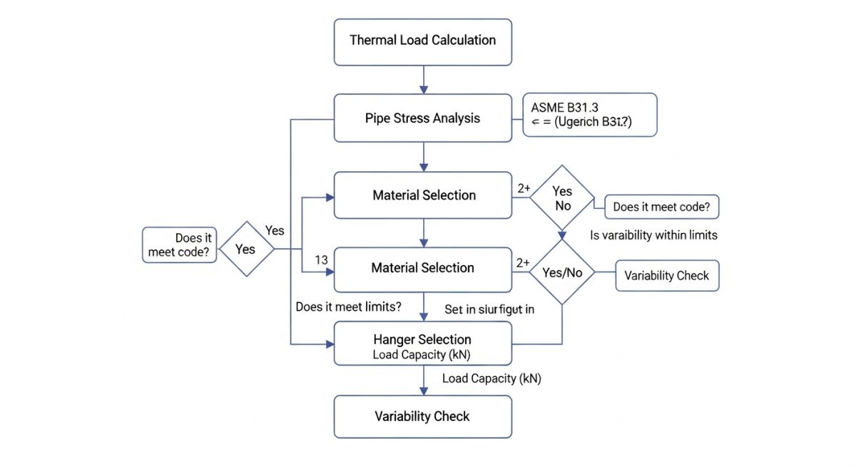
Standard Spring Hanger Selection Parameters
Spring Hanger Parameters: The physical and mechanical limits including travel range, load capacity, and variability tolerances that dictate spring hanger design under MSS SP-58.
| Spring Type | Standard Travel Range (mm) | Load Capacity Range (kN) | Max Variability Limit (%) | Typical Application |
|---|---|---|---|---|
| Short Range (Size 10-20) | 0 to 25 | 0.1 to 50 | 25% | Low thermal movement, non-critical lines |
| Medium Range (Size 30-60) | 0 to 50 | 0.5 to 120 | 25% | Standard process piping, moderate thermal expansion |
| Double Range (Size 70-90) | 0 to 100 | 1.0 to 200 | 25% | High vertical movement, steam headers |
| Constant Effort Hanger | 50 to 500+ | 0.5 to 400 | 6% (per MSS SP-58) | Critical steam lines, turbine connections |
| Entity / Acronym | Physical Parameter | Governing Standard | Stress Analysis Role |
|---|---|---|---|
| Operating Load (P_op) | Force (N or lbs) | ASME B31.3 | Determines the hot load support requirement during operation. |
| Cold Load (P_cold) | Force (N or lbs) | MSS SP-58 | The load exerted by the spring during installation and shutdown. |
| Spring Rate (k) | Stiffness (N/mm or lbs/in) | Manufacturer Catalog | Controls the rate of load change per unit of thermal displacement. |
| Thermal Travel (dy) | Displacement (mm or in) | ASME B31.1 / B31.3 | Calculated vertical movement of the pipe from ambient to operating temperature. |
Field Verification for Spring Hanger Pipe Support Selection
Field Verification Protocol: The mandatory on-site inspection steps required to validate spring hanger installation, preset travel stops, and cold-to-hot load transitions in compliance with ASME B31.3.
Even the most perfect CAESAR II stress model is useless if the field installation is flawed. In my experience, field construction crews frequently make mistakes during the installation of spring hangers. They might leave the travel stops locked, install the hanger upside down, or fail to adjust the turnbuckle to achieve the correct cold load setting.
To prevent catastrophic piping failures during commissioning, use this field verification checklist before hydrostatic testing and plant startup.
Spring Hanger Field Commissioning Checklist
-
Verify Model and Tag Number: Cross-reference the physical spring hanger tag with the piping isometric drawing and the CAESAR II stress report.
-
Confirm Travel Stop Status: Ensure the factory-installed travel stops (locking pins) remain securely in place during hydrostatic testing.
-
Check Cold Load Setting: Verify that the load indicator pointer aligns perfectly with the “C” (Cold) mark on the hanger scale plate before heating the system.
-
Remove Travel Stops Post-Hydrotest: Ensure all travel stops are completely removed *after* the hydrotest is complete and *before* the system is heated up.
-
Inspect Hot Load Alignment: Once the system reaches its operating temperature, verify that the load indicator pointer aligns with the “H” (Hot) mark.
-
Check Angular Deviation: Ensure the hanger rod angular deviation does not exceed 4 degrees from the vertical axis to prevent binding.
Field Case Study: Real-World Application
Stress Analysis Case Study: A practical evaluation of a high-temperature steam line where incorrect spring selection led to excessive nozzle loading and subsequent system redesign.
The Problem: Overloaded Steam Turbine Nozzle
During the commissioning of a 120 MW steam turbine piping system, the field team noticed that the turbine casing was experiencing severe vibration. The steam line was operating at 540 degrees Celsius. A quick review of the stress analysis model revealed that the designer had selected a standard variable spring hanger with a high spring rate. The vertical thermal expansion at the header was 45 mm. Because of this high displacement and the stiff spring, the calculated load variability was 38%, which far exceeded the 25% limit. This transferred an massive unbalanced force of 18 kN directly onto the turbine inlet nozzle, causing casing distortion and shaft misalignment.
The Solution & Outcome
I was brought in to troubleshoot the system. I immediately revised the CAESAR II model, replacing the stiff variable spring hanger with a constant effort spring hanger. This reduced the load variability from 38% to less than 5%. The unbalanced force on the turbine nozzle dropped from 18 kN to a negligible 1.2 kN, which was well within the allowable limits specified by API 611 / API 612. The field team installed the constant spring, removed the travel stops, and restarted the turbine. The vibration levels dropped to baseline, saving the client from a multi-million dollar equipment failure.
My recommendation is simple: never treat spring hanger selection as an afterthought. If your thermal displacement exceeds 25 mm, or if you are supporting piping near sensitive rotating equipment, always perform a rigorous variability check and opt for constant effort supports when necessary.
Frequently Asked Engineering Questions
Spring Hanger FAQ: A compiled reference of critical technical answers addressing variability calculations, constant support selection, and stress analysis modeling rules.
What is the maximum allowable load variability for variable spring hangers?
When should I choose a constant spring hanger over a variable spring hanger?
How does CAESAR II calculate the cold and hot loads for spring selection?
Why must travel stops remain installed during hydrostatic testing?
What is the significance of the spring rate in hanger selection?
Can a spring hanger be used to support lateral or horizontal piping loads?
===
Complete Course on
Piping Engineering
Check Now
Key Features
- 125+ Hours Content
- 500+ Recorded Lectures
- 20+ Years Exp.
- Lifetime Access
Coverage
- Codes & Standards
- Layouts & Design
- Material Eng.
- Stress Analysis
