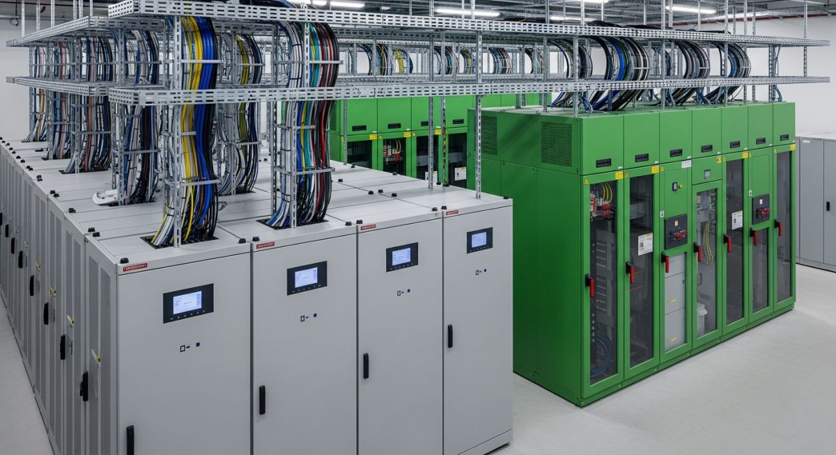
Power Systems in Data Centres: Engineering for 99.999% Uptime
In my two decades of experience designing industrial and mission-critical facilities, I have learned that the power systems in data centres are the heartbeat of the digital economy. A single millisecond of power instability can trigger a cascading failure in server racks, leading to catastrophic data loss and massive financial penalties. Designing these systems requires more than just sizing cables; it demands a rigorous approach to fault tolerance, harmonic mitigation, and thermal management.
This guide explores the complex architecture of modern data centre power distribution, from the medium-voltage utility entrance to the rack-level power distribution units. We will dissect the engineering principles that allow facilities to maintain operations during utility outages, equipment failures, or routine maintenance cycles.
Key Engineering Takeaways
- Understanding the N+1 and 2N redundancy models for high-availability design.
- Mitigating harmonic distortion caused by high-density server power supplies.
- Optimizing the transition time between utility power and standby generator sets.
- Implementing IEEE 1100 standards for grounding and sensitive electronic equipment protection.
Engineering Power Systems in Data Centres: Design and Reliability
Power Systems in Data Centres: The technical framework governing the conversion, distribution, and protection of electrical energy to maintain constant voltage and frequency stability for IT infrastructure.
Designing robust power systems in data centres requires a deep understanding of the electrical path from the utility substation to the individual server power supply unit. In my practice, I prioritize the “Total Cost of Ownership” (TCO) alongside reliability, ensuring that the electrical infrastructure is not only redundant but also energy-efficient. The primary challenge lies in managing the non-linear loads presented by modern server power supplies, which often exhibit high crest factors and significant harmonic content.
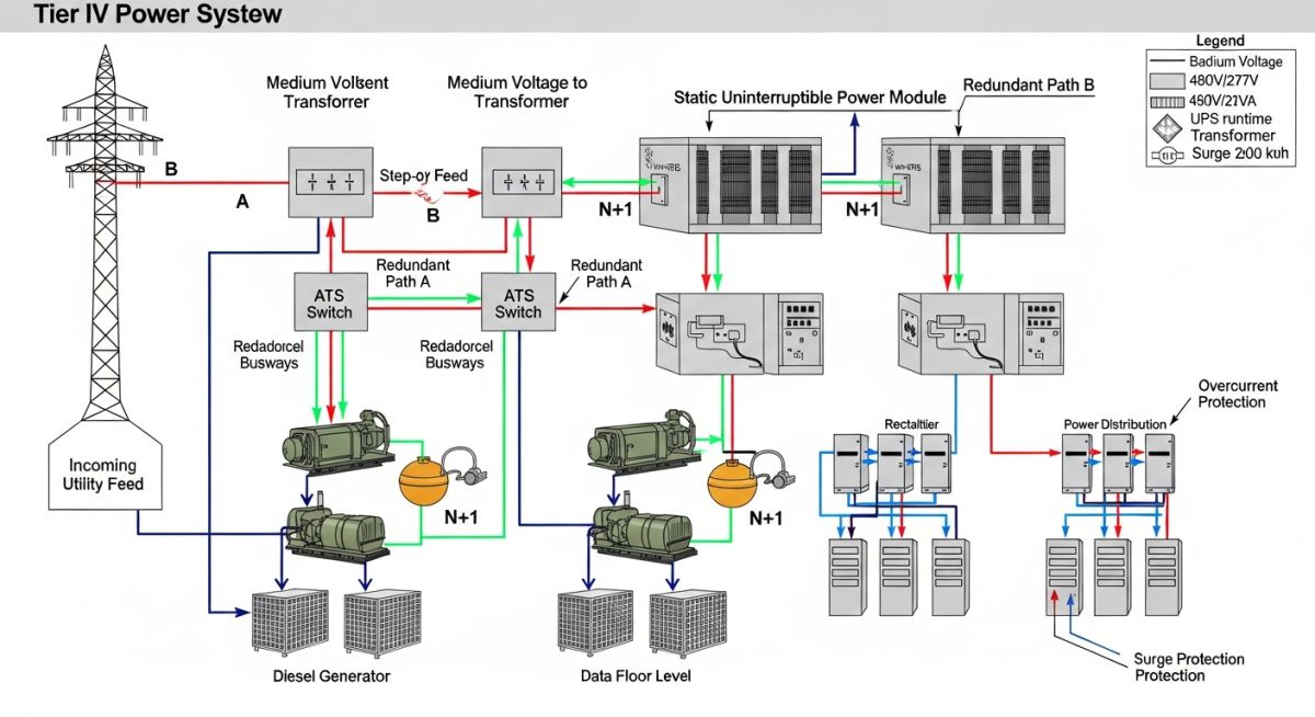
Utility Power and Medium-Voltage Distribution
The utility entrance serves as the foundation of the facility’s power architecture. We typically design for dual-utility feeds, often sourced from independent substations to mitigate the risk of a single-point failure in the grid. The medium-voltage switchgear must be rated for the total facility load plus a 20% growth margin, adhering to ANSI/NETA testing standards.
Field Warning: Harmonic Mitigation
High-density server loads generate significant total harmonic distortion (THD). If not addressed via K-rated transformers or active harmonic filters, this distortion can lead to overheating in neutral conductors and premature failure of UPS capacitors. Always specify transformers with electrostatic shielding to provide common-mode noise attenuation.
UPS Systems and Energy Storage
The Uninterruptible Power Supply (UPS) is the critical bridge between utility failure and generator startup. I generally specify double-conversion online UPS systems, which provide the highest level of power conditioning. The sizing calculation must account for the power factor of the IT load, which is typically leading in modern high-density servers. The formula for sizing is: UPS kVA = (Total IT Load kW / Power Factor) * Safety Factor. A safety factor of 1.25 is standard to accommodate future load growth and transient inrush currents.
Backup Generation and Redundancy
Backup generators must be sized to handle the full load of the facility, including cooling systems. The transition from utility to generator is managed by Automatic Transfer Switches (ATS). In a 2N configuration, each side of the power distribution path is fully independent, meaning the failure of any single component—or even an entire power train—does not interrupt the IT load. This level of redundancy is the gold standard for Tier IV facilities.
Redundancy Architecture Trade-offs: The engineering balance between capital expenditure, operational complexity, and the statistical probability of system downtime in mission-critical electrical environments.
Advantages of High-Redundancy Systems
- Elimination of single points of failure through 2N topology.
- Ability to perform concurrent maintenance on UPS and switchgear without load interruption.
- Enhanced power quality through double-conversion UPS conditioning.
- Scalability for future high-density compute requirements.
- Improved fault isolation via sophisticated circuit breaker coordination.
Disadvantages of High-Redundancy Systems
- Significant increase in initial capital expenditure (CAPEX).
- Higher operational energy losses due to redundant equipment idling.
- Increased complexity in control logic and synchronization.
- Larger physical footprint requirements for dual-path infrastructure.
- Higher maintenance costs due to the increased number of active components.
Mission-Critical Power Deployment: The strategic application of redundant electrical topologies across diverse sectors requiring continuous uptime and high-availability data processing.
Financial Services High-Frequency Trading
In the financial sector, latency is measured in microseconds, and power stability is non-negotiable. These facilities utilize ultra-fast static transfer switches and flywheel-based energy storage to provide instantaneous power support, ensuring that trading algorithms remain active during even the most minor voltage sags.
Hyperscale Cloud Infrastructure
Hyperscale data centres prioritize modular power distribution to allow for rapid capacity expansion. By utilizing containerized power skids and standardized busway systems, these facilities can deploy massive amounts of compute power while maintaining strict N+1 redundancy across the entire electrical distribution chain.
Healthcare Electronic Health Records (EHR)
Hospitals require high-availability data centres to manage patient records and diagnostic imaging in real-time. These systems are often integrated with the hospital’s emergency power grid, requiring complex synchronization between the data centre UPS and the facility-wide backup generators to ensure life-safety compliance.
In my two decades of field experience, selecting the correct electrical infrastructure requires a granular understanding of how individual components interact under transient load conditions. The table below outlines the critical performance parameters for primary power equipment, specifically focusing on efficiency ratings and typical response times during a utility failure event. These values are derived from IEEE standards and common industry benchmarks for Tier III and Tier IV facilities.
Engineers must note that while nominal efficiency is often cited by manufacturers, the actual operational efficiency varies significantly based on the load profile of the server racks. When designing for high-density environments, I always recommend applying a derating factor to these nominal values to account for harmonic distortion and thermal degradation over the equipment’s lifecycle. Always cross-reference these figures with the specific NFPA 70 requirements for your local jurisdiction.
The following matrix serves as a technical cross-reference for the complex ecosystem of Power Systems in Data Centres. As an engineer, I find that maintaining a clear mapping between physical hardware, logical redundancy levels, and the governing regulatory standards is the only way to prevent catastrophic design oversights. This matrix organizes these entities to assist in the procurement and commissioning phases of large-scale data centre projects.
By aligning these parameters, you can ensure that your facility’s power architecture remains compliant with the Uptime Institute Tier classifications. Note that the “Criticality Index” provided here is a subjective measure based on the impact of component failure on the overall facility availability, which should be adjusted based on your specific site risk assessment and business continuity requirements.
Verification of Power Systems in Data Centres requires a systematic approach to ensure that every link in the power chain is robust. In my experience, the most common failures occur during the transition from utility to generator power, often due to improper synchronization or harmonic interference. Use this checklist during the commissioning phase to validate that your installation meets the design intent and safety requirements.
- Harmonic Analysis: Verify that the total harmonic distortion (THD) at the PDU input remains below 5% under full load conditions.
- ATS Synchronization: Confirm that the Automatic Transfer Switch correctly senses utility failure and initiates generator start-up within the specified 10-second window per NFPA 110.
- Grounding Integrity: Perform a fall-of-potential test on the facility grounding grid to ensure resistance to earth is below 5 ohms.
- UPS Battery Health: Validate that the battery management system (BMS) is reporting accurate state-of-charge and state-of-health metrics for all strings.
- Thermal Imaging: Conduct infrared thermography on all switchgear connections under load to identify potential hot spots before they lead to arcing.
Beyond these physical checks, ensure that all maintenance logs are updated and that the facility operations team has been trained on the specific emergency shutdown procedures. A well-designed system is only as reliable as the personnel managing it. Always document the results of these tests in a formal commissioning report, which should be signed off by the lead electrical engineer and the facility manager.
Field Case Study: Real-World Application
The Problem: Unplanned Downtime During Utility Switching
A Tier III data centre experienced intermittent server reboots during the transition from utility power to backup generator power, despite having a redundant UPS system in place.
- Incompatible phase synchronization between the utility grid and the standby generator.
- Incorrect settings on the Automatic Transfer Switch (ATS) causing a momentary break in power.
- High inrush currents from the server power supplies exceeding the UPS bypass capacity.
- Lack of proper harmonic filtering leading to voltage spikes during the transfer event.
The Outcome: Achieving 99.999% Reliability
After a comprehensive root cause analysis, we implemented a series of corrective measures that stabilized the power environment and eliminated the reboots.
- Installed a digital synchronizer to match the generator frequency and phase with the utility grid.
- Reconfigured the ATS to a closed-transition mode, ensuring no break in power during the transfer.
- Upgraded the UPS firmware to better handle high-inrush current profiles of modern server hardware.
- Implemented a continuous power quality monitoring system to detect and log transients in real-time.
My recommendation for similar facilities is to prioritize the integration of power quality monitoring at the branch circuit level. By capturing data at the rack level, you can identify potential issues before they propagate to the main switchgear, allowing for proactive maintenance rather than reactive troubleshooting.
Frequently Asked Engineering Questions
What is the difference between N+1 and 2N redundancy?
- N+1 is cost-effective but leaves the system vulnerable during maintenance of the common bus.
- 2N offers full fault tolerance, allowing any single component or path to be taken offline without impacting the load.
- For mission-critical facilities, 2N is the industry standard to ensure continuous uptime during both failures and scheduled maintenance.
How do I calculate the required UPS battery runtime?
- Identify the total load (kW) and the desired autonomy time (usually 5 to 15 minutes).
- Consult the manufacturer’s discharge tables, which account for the end-of-discharge voltage and temperature.
- Always include a 20% safety margin to account for battery aging and potential capacity loss over the service life.
Why is harmonic distortion a concern for data centres?
- Excessive harmonics cause overheating in transformers and neutral conductors.
- They can lead to nuisance tripping of circuit breakers and erratic behavior in sensitive electronic controls.
- Using K-rated transformers and active harmonic filters is the standard approach to mitigating these effects in high-density environments.
What are the benefits of modular UPS systems?
- They offer high availability because individual modules can be hot-swapped without shutting down the load.
- Maintenance is simplified as technicians can replace a single module rather than servicing the entire unit.
- The footprint is generally smaller, allowing for better space utilization in constrained white space environments.
How often should backup generators be tested?
- Weekly no-load runs are recommended to verify starting capability and check for fluid leaks.
- Monthly load bank testing is essential to prevent “wet stacking” and ensure the engine can handle the rated load.
- Annual full-load transfer tests are required to confirm that the entire power chain, including the ATS and switchgear, functions as a cohesive system.
What is the role of a PDU in power distribution?
- It provides step-down transformation, voltage regulation, and local circuit protection.
- Modern PDUs include intelligent monitoring features that track power usage effectiveness (PUE) at the rack level.
- They are critical for managing cable density and ensuring that power is distributed safely and efficiently to high-density server blades.
Complete Course on
Piping Engineering
Check Now
Key Features
- 125+ Hours Content
- 500+ Recorded Lectures
- 20+ Years Exp.
- Lifetime Access
Coverage
- Codes & Standards
- Layouts & Design
- Material Eng.
- Stress Analysis

📚 Recommended Resources: Power Systems in Data Centres
Read these Guides
- 📄 Edge Data Centres Explained: Infrastructure Design and Deployment Strategies
- 📄 Hyperscale Data Centre Engineering: Design Principles and Infrastructure Requirements
- 📄 Understanding Data Centre Types: Enterprise, Colocation, Hyperscale, and Edge
- 📄 How Data Centres Work: Infrastructure and Operations Engineering Overview