The Ultimate Guide to Plot Plan Drawing Optimization in 2026
What You Will Master:
- ✔️ The Plot Plan Drawing serves as the primary document for defining battery limits and equipment coordinates.
- ✔️ Integration of ASME and API spacing standards to ensure operational safety and maintenance access.
- ✔️ Optimization of piping runs and civil grading through effective spatial planning and orientation.
What is a Plot Plan Drawing?
A Plot Plan Drawing is a master engineering document providing a top-down view of a facility’s layout. It defines the precise location, coordinates, and orientation of equipment, structures, and piperacks. It establishes battery limits, ensures safety clearances per standards like NFPA, and facilitates efficient construction and maintenance workflows.
“In my two decades of plant design, I’ve seen projects fail not because of thermodynamics, but because of poor spatial coordination. A Plot Plan Drawing isn’t just a map; it’s a strategic asset that dictates 70% of your piping costs and 100% of your maintenance accessibility.”
— Atul Singla, Founder
Complete Course on
Piping Engineering
Check Now
Key Features
- 125+ Hours Content
- 500+ Recorded Lectures
- 20+ Years Exp.
- Lifetime Access
Coverage
- Codes & Standards
- Layouts & Design
- Material Eng.
- Stress Analysis
Plot Plan Engineering IQ Test
Validate your expertise in industrial spatial design
Which standard primarily governs the safety spacing distances on a Plot Plan Drawing for oil and gas facilities?
Quiz Complete!
You have mastered the fundamentals of the Plot Plan Drawing.
Comprehensive Definition of a Plot Plan Drawing
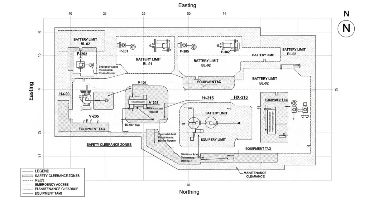
In the sophisticated realm of industrial architecture, a Plot Plan Drawing serves as the definitive spatial constitution for any process facility. Unlike a simple architectural site plan, this engineering document is a precision-scaled 2D representation that dictates the absolute coordinates (Eastings and Northings) for every piece of static and rotary equipment. It integrates complex multi-disciplinary data, ensuring that the physical arrangement adheres to stringent safety codes such as API RP 752 for building locations and NFPA 30 for tank storage. By establishing the Plot Plan Drawing early in the Front-End Engineering Design (FEED) phase, engineers create a frozen layout that governs the downstream development of piping isometrics, civil foundation designs, and electrical cable tray routing.
The Plot Plan Drawing is essentially a top-down “map” of the plant’s “Battery Limit”—a designated boundary that separates specific process units from the rest of the facility or offsite utilities. It is the primary tool used by Piping Lead Engineers to minimize “pipe rack congestion” and optimize the “NPSH” (Net Positive Suction Head) available for pumps by strategically placing vessels and tanks. For a deep dive into the regulatory framework governing these layouts, engineers frequently reference the ASME Official Standards to ensure structural and pressure integrity across the plant footprint.
Industrial Applications of Plot Plan Drawing Design
The application of a Plot Plan Drawing extends far beyond simple equipment placement; it is a live document used throughout the entire project lifecycle. During the Construction Phase, the plot plan is utilized for “Heavy Lift” planning, identifying where cranes can be positioned without compromising underground utilities or existing foundations. In Operational Phases, it serves as the master reference for Emergency Response Plans (ERP), highlighting muster points, fire hydrant locations, and hazardous zone classifications (Hazardous Area Classification).
Furthermore, in “Brownfield” projects (modifying existing plants), the Plot Plan Drawing is critical for “Tie-in” management. It allows engineers to visualize how new equipment modules will interface with legacy systems without causing physical clashes. By utilizing Plot Plan Drawing strategies, EPC (Engineering, Procurement, and Construction) firms can significantly reduce field rework, which often accounts for up to 15% of total project cost overruns.
Primary Types of Plot Plan Drawing Formats
Depending on the project stage and detail required, a Plot Plan Drawing usually manifests in three distinct formats:
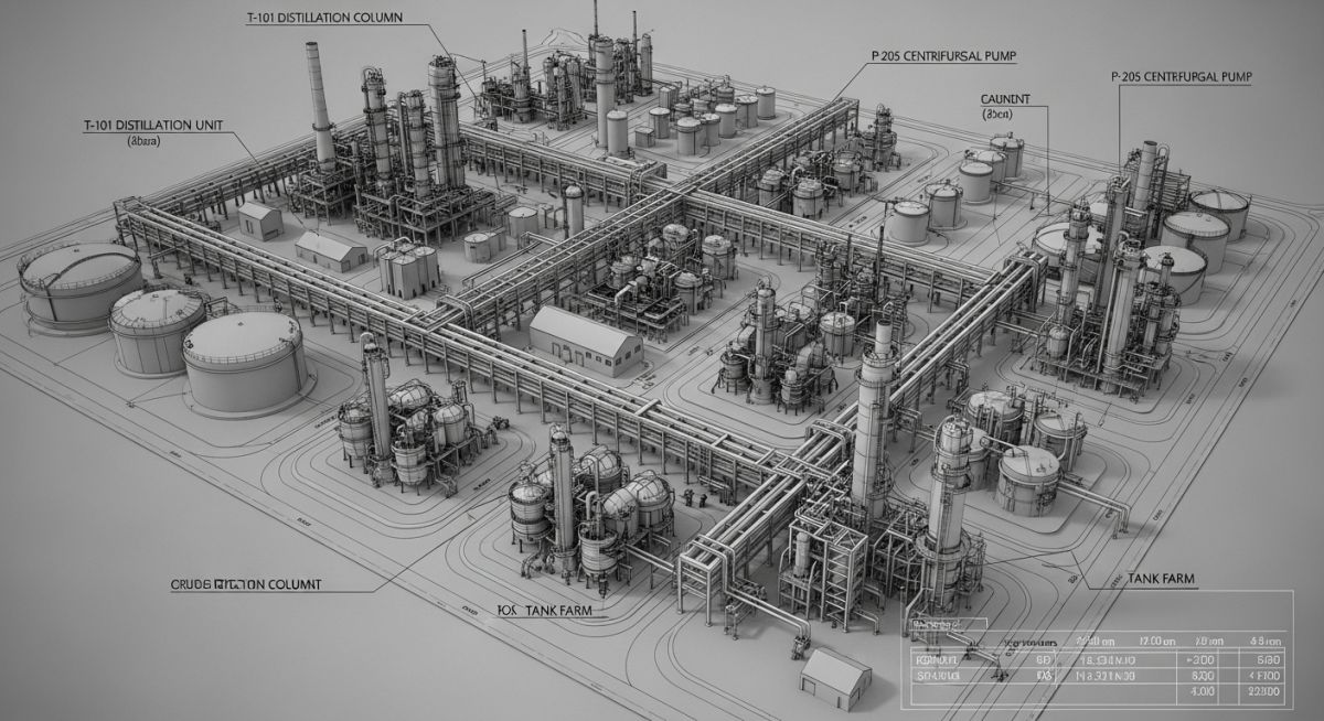
- Overall Plot Plan: A macro-level view showing the entire site, including administrative buildings, flare stacks, tank farms, and main access roads.
- Unit Plot Plan: A micro-level detailed drawing of a specific process unit (e.g., a Crude Distillation Unit) within the battery limits, showing individual pump coordinates and nozzle orientations.
- Conceptual Plot Plan: Developed during the feasibility study to estimate the required land acreage and preliminary environmental impact.
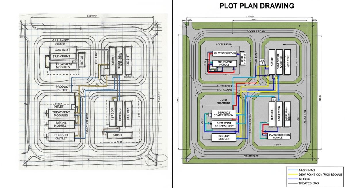
Essential Engineering Inputs for Plot Plan Drawing Development
The development of a high-fidelity Plot Plan Drawing is a multidisciplinary synthesis. It cannot be created in isolation; rather, it requires a “frozen” set of data from process, civil, and mechanical teams. The most critical input is the Piping and Instrumentation Diagram (P&ID), which dictates the functional relationship between equipment. For instance, gravity-flow lines identified in the P&ID necessitate specific elevation differentials that must be captured in the Plot Plan Drawing coordinates.
Furthermore, Process Data Sheets provide the physical dimensions and weights of equipment, while the Hazardous Area Classification schedule informs the mandatory separation distances required by API RP 500. Failure to integrate these inputs early results in “Layout Recycles,” where piping must be rerouted late in the design phase, exponentially increasing costs. To verify specific spacing requirements for fire safety, engineers often consult the NFPA Official Standards to ensure legal compliance.
Key Technical Information Contained in a Plot Plan Drawing
A standard Plot Plan Drawing is a dense information hub. It must contain the following “Non-Negotiables” to be considered a construction-ready document:
| Component | Technical Requirement | Governing Standard |
|---|---|---|
| Equipment Coordinates | Centerline (C/L) of vessels and pumps based on Plant North. | ISO 15519 |
| Safety Distances | Clearance between high-pressure units and ignition sources. | API RP 752 / NFPA 30 |
| Battery Limits | Geographic boundary lines for contractual scope. | Project Spec |
| Access Roads | Minimum 6m width for fire tender access. | OSHA 1910 |
Engineering Workflow: Finalizing the Plot Plan Drawing
The workflow for a Plot Plan Drawing typically follows a “Check-Review-Approve” cycle. Once the initial layout is drafted, it undergoes a Constructability Review where field experts simulate equipment installation using crane radius charts. Following this, a 30% Model Review (in tools like SP3D or E3D) ensures that the 2D Plot Plan Drawing matches the 3D reality. This rigorous process minimizes the risk of interferences between structural steel and piping headers.
Equipment Spacing & Plot Area Estimator
Based on API RP 752 / NFPA 30 Safety Guidelines for Plot Plan Drawing planning.
*Disclaimer: This tool provides preliminary estimates for Plot Plan Drawing feasibility studies only. Final spacing must be verified against site-specific HAZOP studies and local fire codes.
EPCLand YouTube Channel
2,500+ Videos • Daily Updates
Engineering Case Study: Brownfield Debottlenecking
The Challenge
An aging refinery needed to integrate a new Plot Plan Drawing for a modular Hydrogen Recovery Unit within a 20m x 30m congested corridor.
The Constraints
Existing underground high-voltage cables and overhead 30-inch steam headers limited heavy crane access and foundation depth.
The Solution
A 3D laser-scanned Plot Plan Drawing was generated to identify “Clash-Free” zones for modular skid placement and crane outrigger pads.
Technical Execution & Results
By utilizing a high-fidelity Plot Plan Drawing, the engineering team successfully reduced the piping spool count by 12% through vertical stacking of heat exchangers. The drawing served as the primary coordination tool for the “Heavy Lift” plan, ensuring that the 150-ton module was placed within 5mm of the design coordinates without disturbing the adjacent live unit.
Key Outcome:
Zero field clashes during the 48-hour shutdown window, saving an estimated $1.2 Million in potential downtime penalties.
Don’t miss this video related to Plot Plan

Summary: Master Piping Engineering with our complete 125+ hour Certification Course: ……
Expert Insights: Lessons from 20 years in the field
-
Prioritize “Maintenance Envelopes” Over Footprints
A common rookie mistake is drafting a Plot Plan Drawing based only on equipment dimensions. Always include “Tube Bundle Pulling” space for exchangers and “Rotors Removal” zones for compressors. If it’s not on the drawing, civil will put a pedestal there, and you’ll be chipping concrete in three years.
-
Wind Direction is a Safety Constraint
Never place a Fired Heater downwind of a Hydrocarbon Pump row. Your Plot Plan Drawing must align the “Prevailing Wind” arrow so that potential leaks are carried away from ignition sources, adhering to API RP 752 siting philosophies.
-
Standardize Coordinate Grids Early
Ensure the Plot Plan Drawing uses the “Global Project Coordinate System” from day one. Converting local plant grids to global coordinates mid-project is the fastest way to introduce 500mm errors in piping tie-ins.
Frequently Asked Questions: Plot Plan Drawing
What are the primary objectives of a Plot Plan Drawing?
How does a Plot Plan Drawing differ from a Site Plan?
At what project stage is the Plot Plan Drawing finalized?
Why must the Plot Plan Drawing consider the “Prevailing Wind”?
What happens if a Plot Plan Drawing ignores “Tube Bundle Pulling”?
Can I use GPS coordinates directly on a Unit Plot Plan?
📚 Recommended Resources: Plot Plan
Read these Guides
🎓 Advanced Training


Related posts:
![High-grade industrial Wing Nut Types and Applications for mechanical assemblies.]()
Wing Nut Types and Applications: The 2026 Engineering Guide
![Industrial Monorail Crane Systems installed in a modern manufacturing plant 2026.]()
Monorail Crane Systems: Design, Types & 2026 Standards Guide
![Lead engineer performing a Factory Acceptance Test FAT on an industrial skid system 2026]()
Factory Acceptance Test FAT: The 2026 Engineering Guide to Zero-Defect Delivery
![Professional engineering workspace showing a Basis of Design document layout for a 2026 project.]()
Basis of Design: How to Write a BOD for Engineering Projects in 2026
![Industrial Flare Knockout Drum Sizing and installation in a refinery relief system.]()
Flare Knockout Drum Sizing: Design & API 521 Standards (2026 Guide)
![Advanced Reboiler Control Systems in a modern petrochemical refinery 2026.]()
Reboiler Control Systems: Engineering Guide to Precision Control 2026


