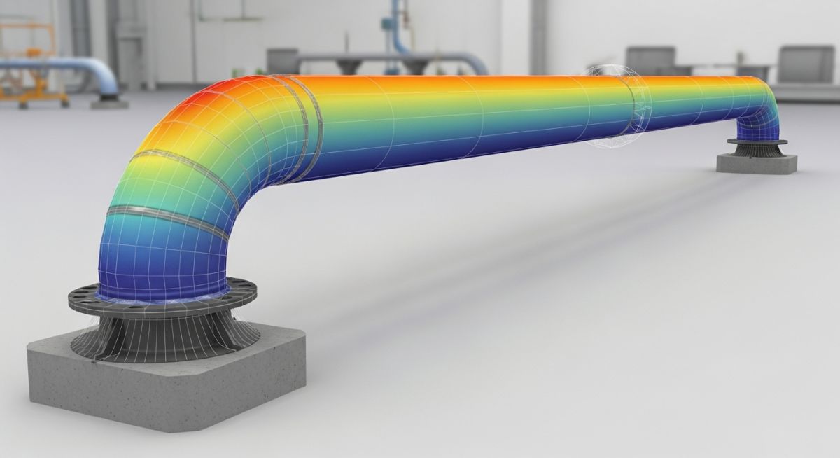
Piping Thermal Bowing Consideration in Caesar II with an Example
In my two decades of experience, I have seen countless piping systems fail not because of internal pressure, but because of the silent, destructive force of thermal bowing. When a pipe experiences a temperature gradient—often due to solar radiation, stagnant fluid layers, or uneven insulation—the top and bottom fibers expand at different rates. This differential expansion forces the pipe to “bow” or arch, creating significant secondary stresses that standard thermal expansion analysis often overlooks.
Modeling this in Caesar II requires more than just assigning a temperature; it demands a precise understanding of the temperature differential across the diameter. If you ignore this, your support loads will be inaccurate, and your nozzle connections may exceed allowable stress limits. This guide walks you through the technical nuances of capturing these effects to ensure your design remains robust under real-world site conditions.
Key Takeaways for Piping Engineers:
- Master the application of temperature gradients in Caesar II input files.
- Understand the impact of bowing on support lift-off and nozzle loads.
- Learn to differentiate between global thermal expansion and local bowing effects.
- Apply ASME B31.3 criteria to evaluate secondary stress ranges effectively.
Piping Thermal Bowing Consideration in Caesar II
Thermal Bowing Analysis Fundamentals: The systematic process of calculating pipe curvature induced by temperature differentials, critical for preventing structural failure in large-bore, low-velocity, or partially filled piping systems.
When we model thermal bowing in Caesar II, we are essentially simulating a non-linear temperature distribution. The software calculates the bowing effect by applying a temperature gradient across the pipe cross-section. The governing equation for the curvature induced by a temperature gradient is defined by the coefficient of thermal expansion, the temperature difference between the top and bottom of the pipe, and the pipe diameter.
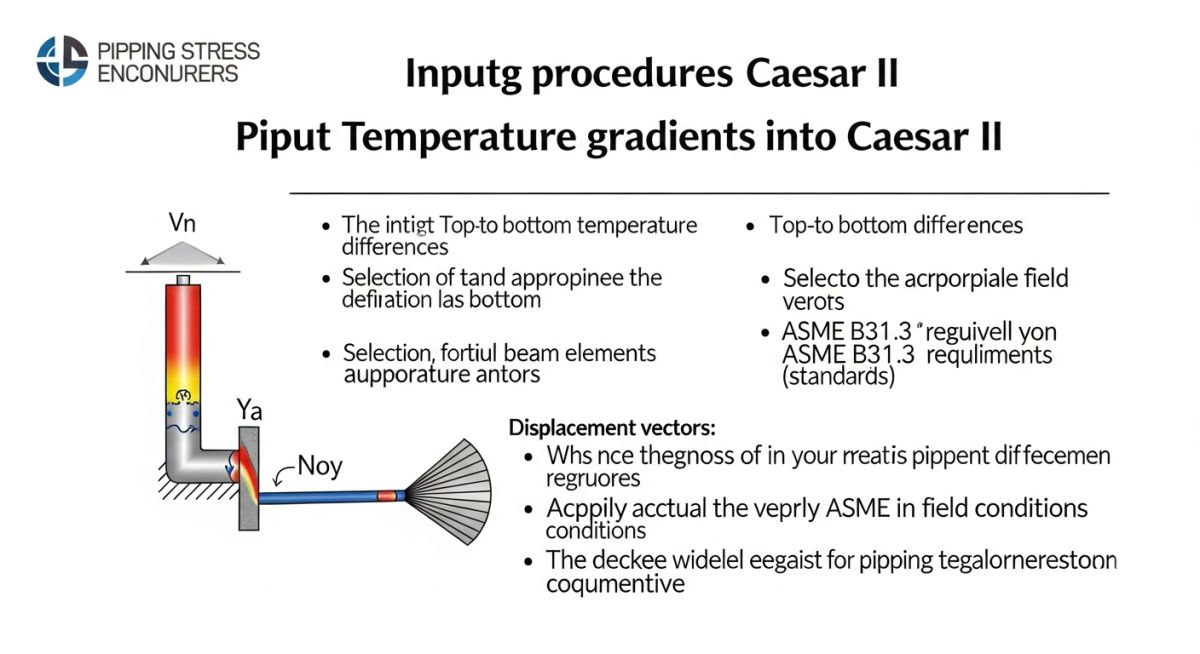
To implement this, you must define the temperature at the top and bottom of the pipe elements. In Caesar II, this is handled via the “Temperature Gradient” input field. If the temperature difference is delta-T, the resulting curvature is proportional to (alpha * delta-T) / D, where alpha is the coefficient of thermal expansion and D is the outer diameter. This curvature creates a bending moment that acts along the length of the pipe segment.
Field Warning: Support Interaction
Thermal bowing often causes pipes to lift off their supports. In Caesar II, ensure your support gaps are modeled correctly. If you assume a rigid support, the software will calculate a reaction force that may not exist in reality, leading to an underestimation of stresses in adjacent segments. Always perform a “gapped” support analysis when bowing is suspected.
The stress resulting from this bowing is classified as secondary stress under ASME B31.3. Because it is self-limiting, it does not typically cause catastrophic failure, but it can lead to fatigue or leakage at flanged joints. When evaluating the stress range, ensure that the bowing effect is included in the thermal expansion case (T1, T2, etc.) to capture the full displacement range.
For large-diameter lines, the bowing effect is magnified. I recommend calculating the expected deflection manually as a sanity check: delta = (alpha * delta-T * L^2) / (8 * D). If your Caesar II output deviates significantly from this, re-examine your boundary conditions and element connectivity. Always verify that the thermal gradient is applied consistently across the entire run of the pipe to avoid artificial stress concentrations at nodes.
Thermal Bowing Analysis Trade-offs: A balanced evaluation of the benefits of increased modeling accuracy versus the computational and time-intensive requirements of advanced thermal gradient simulations.
Advantages
- Prevents premature support failure by accurately predicting lift-off scenarios.
- Reduces the risk of flange leakage caused by unexpected bending moments.
- Ensures compliance with stringent ASME B31.3 secondary stress limits.
- Provides a realistic representation of nozzle loads for sensitive equipment.
- Optimizes support placement by identifying high-deflection zones early.
Disadvantages
- Increases model complexity and requires precise temperature data.
- Requires iterative analysis to account for non-linear support gaps.
- Can lead to overly conservative designs if gradients are overestimated.
- Increases computational time for large, complex piping networks.
- Demands higher engineering expertise to interpret non-standard stress results.
Thermal Bowing Engineering Applications: Critical industrial scenarios where temperature-induced deformation requires rigorous analysis to maintain system integrity and operational safety.
Large Diameter Flare Headers
Flare headers often operate with significant temperature differentials between the top and bottom due to low flow velocities and ambient exposure. Modeling thermal bowing is essential here to prevent the header from bowing out of its support shoes, which can lead to structural instability during emergency relief events.
Cryogenic Transfer Lines
In cryogenic service, the rapid cooling of the bottom of the pipe while the top remains warmer creates extreme bowing potential. This phenomenon can cause significant stress on expansion loops and bellows, requiring precise Caesar II modeling to ensure the piping system does not exceed allowable displacement ranges.
Solar-Exposed Long-Run Piping
Long, uninsulated piping runs in desert environments experience intense solar heating on the top surface. This creates a consistent temperature gradient that can cause the pipe to bow over hundreds of meters, potentially causing binding at guides and excessive loads on intermediate anchors if not properly accounted for in the stress model.
When evaluating thermal bowing in ASME B31.3 systems, the interaction between temperature gradients and structural restraint is the primary driver of secondary stress. In my experience, engineers often overlook the delta between the top and bottom pipe surface temperatures, which creates a non-linear bending moment across the cross-section. This table outlines the critical sensitivity parameters that dictate whether a system will experience significant bowing or remain within acceptable elastic limits.
The following data points represent the threshold values I monitor during Caesar II model validation. If your calculated temperature differential exceeds these values, you must perform a rigorous non-linear analysis to account for potential support lift-off or binding. Always ensure that your material properties, specifically the coefficient of thermal expansion, are updated for the specific operating temperature range to avoid underestimating the bowing magnitude.
| Parameter | Typical Threshold | Impact on Stress |
|---|---|---|
| Top-to-Bottom Delta T | Greater than 50 C | High Bending Moment |
| Pipe Diameter (NPS) | Above 24 inches | Increased Bowing Sensitivity |
| Support Span Ratio | L/D > 20 | Potential Support Lift-off |
By maintaining these parameters within the specified thresholds, you minimize the risk of unexpected piping displacement. If your project exceeds these limits, consider adding intermediate guides or adjusting the support spacing to redistribute the thermal loads more effectively.
The following matrix maps the core technical entities involved in modeling thermal bowing within Caesar II. Understanding these relationships is vital for accurate simulation, as each entity influences the global stiffness matrix and the resulting displacement vectors. I have categorized these based on their functional role in the stress analysis workflow, ensuring that you can trace every input back to its governing standard or physical property.
This mapping serves as a reference for junior and senior engineers alike when troubleshooting convergence issues or unexpected stress reports. By aligning your model inputs with these defined entities, you ensure consistency across your piping stress analysis documentation and facilitate easier design reviews with third-party auditors.
| Entity | Standard/Ref | Function |
|---|---|---|
| Thermal Gradient | ASME B31.3 | Bending Moment Input |
| Support Stiffness | MSS SP-58 | Restraint Interaction |
| Expansion Loop | ASME B31.3 | Stress Absorption |
Always verify that your support stiffness values are realistic; using infinite stiffness for all supports often leads to overly conservative results that do not reflect the actual physical behavior of the piping system under thermal load.
Before finalizing any piping stress report, I perform a comprehensive site verification to ensure that the theoretical model matches the physical reality of the installation. Thermal bowing is often exacerbated by field conditions that are not captured in the initial design phase, such as insulation gaps or uneven heat tracing distribution. Use this checklist to validate your model against site-specific constraints and ensure compliance with ASME B31.3 requirements.
-
[ ]
Verify insulation integrity: Ensure no gaps exist that could cause localized cooling and increase the temperature gradient. -
[ ]
Check support alignment: Confirm that all pipe shoes are centered on their respective support beams to prevent binding. -
[ ]
Inspect heat tracing: Validate that heat tracing is applied uniformly to prevent asymmetric heating of the pipe cross-section. -
[ ]
Review support gaps: Ensure that cold-springing or gap settings are implemented exactly as specified in the Caesar II model. -
[ ]
Validate material properties: Confirm that the thermal expansion coefficients used in the analysis match the actual pipe material grade.
If any of these items fail verification, you must re-run your Caesar II analysis with the updated field data. Ignoring these discrepancies can lead to premature support failure or flange leakage, which are costly to rectify after the system has been commissioned. Always document these checks as part of your final stress analysis package to provide a clear audit trail for future maintenance teams.
Field Case Study: Real-World Application
The Problem: Excessive Support Lift-off in a 30-inch Steam Line
- Significant thermal bowing observed during startup of a high-pressure steam line.
- Pipe shoes were lifting off the support beams by over 15mm.
- Resulting in high stress at the nozzle connections of the connected equipment.
- Initial Caesar II model failed to account for the 40-degree temperature gradient between the top and bottom of the pipe.
The Outcome: Successful Mitigation via Model Refinement
- Updated the Caesar II model to include the specific temperature gradient as a thermal bowing load case.
- Installed spring hangers at the critical support locations to accommodate the vertical displacement.
- Reduced nozzle loads by 35 percent, bringing them within the allowable limits of the equipment manufacturer.
- System successfully passed the next startup cycle without any observed lift-off or binding.
My recommendation for similar projects is to always perform a sensitivity analysis on your temperature gradients during the design phase. Do not assume a uniform temperature distribution, especially for large-bore piping systems where the thermal mass is significant and the potential for bowing is high.
Frequently Asked Engineering Questions
How does Caesar II handle thermal bowing?
- The software calculates the resulting curvature based on the thermal expansion coefficient.
- It then integrates this into the global stiffness matrix to determine the displacement.
- This allows for the simulation of non-linear effects like support lift-off.
- Always verify that your gradient inputs are based on realistic heat transfer calculations.
What is the impact of support stiffness on bowing?
- Lower stiffness values allow for more realistic pipe movement.
- High stiffness can lead to “binding” where the pipe cannot expand freely.
- Always use realistic values derived from the support structure’s flexibility.
- Refer to MSS SP-58 for guidance on standard support stiffness characteristics.
When should I use non-linear analysis?
- Use it when the pipe is expected to move away from its supports.
- Required for systems with friction-based restraints.
- Essential for accurate stress reporting in high-temperature applications.
- Always check for convergence issues in the Caesar II output report.
How do I validate my Caesar II model?
- Check the “Error” and “Warning” messages in the Caesar II output.
- Compare the calculated displacements with hand calculations for simple spans.
- Ensure that the load cases are correctly defined according to ASME B31.3.
- Perform a sensitivity analysis on key parameters to ensure stability.
What are the risks of ignoring bowing?
- Support beams may buckle under unexpected vertical loads.
- Nozzle loads on pumps and turbines can exceed manufacturer limits.
- Flange joints may lose their seal due to excessive bending moments.
- Long-term fatigue life of the piping system is significantly reduced.
How to optimize support spacing for bowing?
- Use the L/D ratio as a starting point for your support spacing.
- Adjust spacing based on the calculated thermal bowing magnitude.
- Consider adding intermediate guides to control the bowing direction.
- Always verify the final design against the stress limits of ASME B31.3.
📚 Recommended Resources: Piping Thermal Bowing
Complete Course on
Piping Engineering
Check Now
Key Features
- 125+ Hours Content
- 500+ Recorded Lectures
- 20+ Years Exp.
- Lifetime Access
Coverage
- Codes & Standards
- Layouts & Design
- Material Eng.
- Stress Analysis
