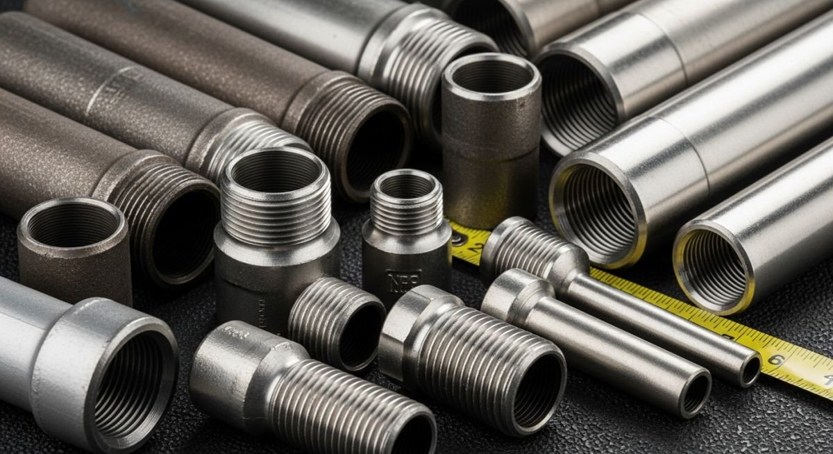
Piping Nipples for Piping and Plumbing Industry: A Technical Guide
In my two decades of field experience, I have seen countless system failures traced back to the improper selection of piping nipples. While they appear to be simple, standardized components, their role in maintaining pressure integrity within a piping network is paramount. Whether you are dealing with high-pressure steam or corrosive chemical lines, understanding the nuances of wall thickness, thread engagement, and material compatibility is non-negotiable.
This guide dissects the technical requirements for specifying these components, ensuring your piping systems meet both safety and operational efficiency benchmarks. We will move beyond basic catalog specs to explore the real-world engineering constraints that dictate long-term reliability in industrial environments.
Key Takeaways
- Master the distinction between close, short, and long nipple configurations.
- Apply ASTM A733 standards to ensure material grade and wall thickness compliance.
- Understand the critical role of NPT thread engagement in preventing leakage.
- Evaluate pressure-temperature ratings based on the base pipe schedule.
Technical Specifications for Piping Nipples
Piping Nipples Engineering: The structural integrity of a nipple is defined by its base pipe material, wall thickness, and thread precision as mandated by ASTM A733.
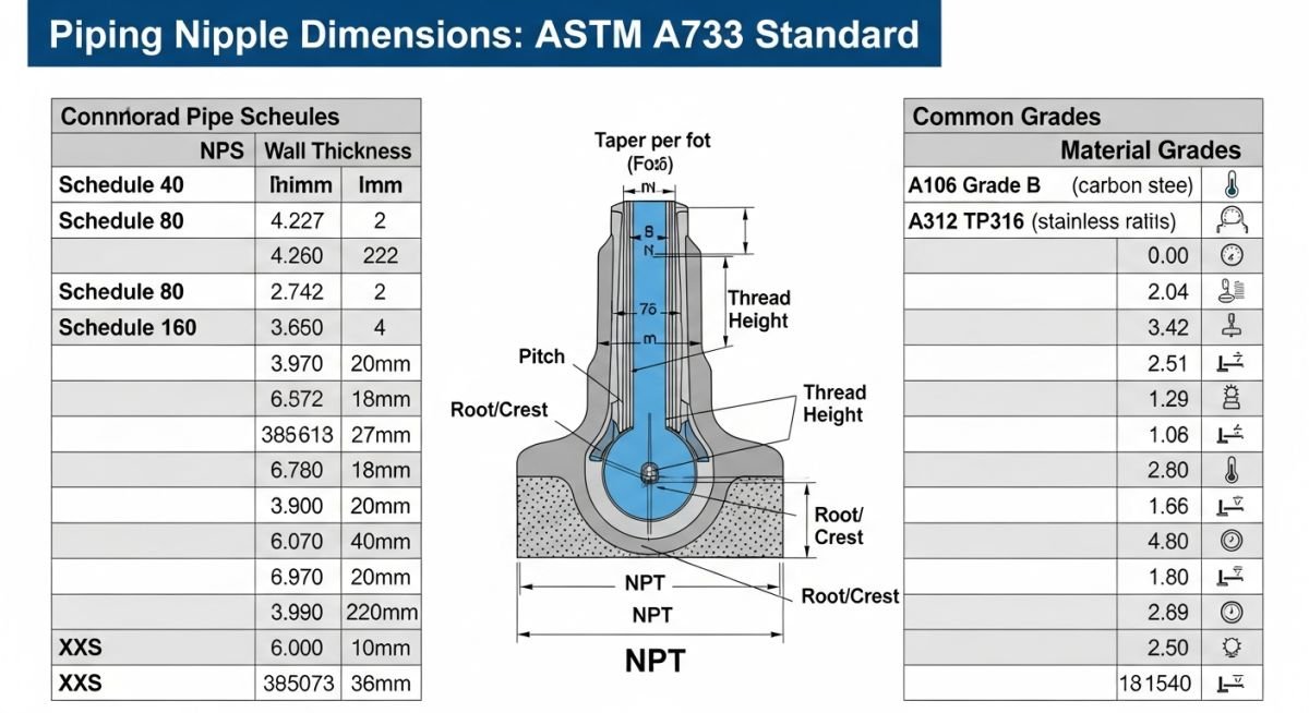
When I specify a nipple, I first look at the base pipe schedule. A nipple is essentially a cut-to-length piece of pipe with threads on both ends. If the base pipe is Schedule 80, the nipple must be manufactured from Schedule 80 pipe to maintain the same pressure-temperature rating. Using a lighter wall nipple in a heavy-wall system creates a localized weak point that is prone to fatigue failure under vibration.
Thread geometry is governed by ASME B1.20.1, which defines the NPT (National Pipe Taper) standard. The taper of 1 in 16 on diameter is crucial for creating a metal-to-metal seal. In my experience, the most common error is over-tightening, which can lead to thread deformation or cracking in the female fitting. Always ensure that the thread engagement length matches the standard requirements to avoid “bottoming out” before a seal is achieved.
Field Warning: Thread Galling
In stainless steel piping systems, thread galling is a frequent issue. I strongly recommend using a high-quality anti-seize lubricant or PTFE tape that is compatible with the process fluid. Never force a connection if you feel resistance, as this often indicates cross-threading or debris in the threads.
For high-pressure applications, I calculate the required wall thickness using the Barlow formula, but I always cross-reference this with the standard dimensions provided in ASME B36.10M. The nipple length is also a critical design factor. A “close” nipple has no unthreaded pipe between the threads, which makes it extremely difficult to install with a standard pipe wrench without damaging the threads. I prefer using “short” or “long” nipples whenever space permits to allow for proper tool engagement.
Material selection must align with the piping class. For carbon steel, ASTM A106 Grade B is the industry standard. For corrosive environments, I specify ASTM A312 stainless steel. Always verify the heat number and material test report (MTR) to ensure the nipple matches the piping system’s metallurgy, preventing galvanic corrosion at the connection point.
Nipple Performance Characteristics: Evaluating the operational benefits and inherent limitations of threaded nipple connections in industrial piping infrastructure.
Advantages
- Rapid installation compared to welded connections.
- Ease of maintenance and component replacement.
- Cost-effective for small-bore piping systems.
- Standardized dimensions ensure global interchangeability.
- No specialized welding equipment required on-site.
Disadvantages
- Potential for leakage at threaded interfaces.
- Reduced wall thickness at the root of the thread.
- Susceptibility to vibration-induced fatigue failure.
- Limited pressure ratings compared to butt-welded joints.
- Risk of thread galling in stainless steel materials.
Industrial Nipple Deployment: Strategic implementation of threaded nipples across diverse process and utility piping sectors.
Instrumentation and Control Loops
Nipples are the backbone of instrumentation piping, connecting pressure transmitters and gauges to the main process line. I prioritize using high-grade stainless steel nipples here to prevent corrosion-induced signal drift and ensure long-term measurement accuracy in harsh environments.
Utility Steam and Condensate Systems
In steam distribution, thermal expansion is a constant challenge that stresses threaded joints. I specify heavy-wall Schedule 80 nipples for these applications to withstand the cyclic thermal loading and prevent premature thread failure caused by condensate-induced water hammer.
Chemical Injection and Dosing Lines
Chemical dosing systems require precise, leak-free connections to maintain process chemistry. By utilizing nipples with NPT threads and compatible thread sealants, we ensure that aggressive chemicals remain contained, protecting both the facility personnel and the surrounding infrastructure from leaks.
Selecting the correct piping nipple requires a rigorous understanding of the relationship between wall thickness, thread engagement, and pressure-temperature ratings. In my experience, engineers often overlook the fact that the pressure rating of a nipple is not solely determined by the pipe schedule but by the integrity of the threaded connection under cyclic loading. When referencing ASME B1.20.1 for NPT threads, we must ensure that the effective thread length is maintained to prevent leakage in high-pressure hydrocarbon or steam services.
The following table outlines standard dimensions for common pipe schedules. Note that for Schedule 80 and higher, the reduction in cross-sectional area due to threading becomes a critical factor in the piping stress analysis. Always verify that the nipple material grade, typically governed by ASTM A733, matches the parent pipe material to avoid galvanic corrosion or mismatched thermal expansion coefficients in your piping system design.
| Nominal Pipe Size | Schedule | Wall Thickness (in) | Thread Length (in) |
|---|---|---|---|
| 0.5 inch | 80 | 0.147 | 0.75 |
| 1.0 inch | 80 | 0.179 | 0.98 |
| 2.0 inch | 80 | 0.218 | 1.00 |
The engineering landscape for piping components is defined by a complex interplay of material standards, dimensional tolerances, and pressure-containment requirements. To effectively manage the procurement and installation of piping nipples, one must map the specific application requirements against the governing codes. This matrix serves as a technical bridge between the physical hardware and the regulatory framework that ensures safety in industrial environments.
By aligning your project specifications with these recognized standards, you mitigate the risk of premature component failure. Whether you are dealing with carbon steel, stainless steel, or alloy materials, the following matrix categorizes the essential parameters that every piping engineer must validate during the design and inspection phases of a project.
| Entity | Standard | Primary Function |
|---|---|---|
| NPT Threads | ASME B1.20.1 | Pressure-tight sealing |
| Nipple Dimensions | ASTM A733 | Standardized length/wall |
| Pipe Material | ASTM A106 | Seamless carbon steel |
Field installation of piping nipples is often where the most critical errors occur, particularly regarding thread engagement and material compatibility. Before authorizing the installation of any nipple in a pressurized system, I require a thorough verification process to ensure that the component meets the design intent and safety requirements. This checklist is designed to be used by site inspectors and piping supervisors to validate the integrity of the installation before the system is pressurized or commissioned.
- 1. Verify that the nipple material grade matches the piping specification (e.g., ASTM A106 Grade B).
- 2. Inspect threads for burrs, damage, or improper taper as per ASME B1.20.1 requirements.
- 3. Confirm the wall thickness (Schedule) is sufficient for the design pressure and temperature.
- 4. Ensure the thread sealant used is compatible with the process fluid and temperature range.
- 5. Check for proper thread engagement depth to prevent mechanical failure under vibration.
- 6. Validate that the nipple length allows for adequate clearance for maintenance and future removal.
Following these steps ensures that the piping system remains compliant with industry standards and reduces the likelihood of leaks or catastrophic failures. Always document the inspection results in the project quality control log, noting any deviations from the original design specifications. If a nipple shows signs of corrosion or thread deformation during installation, it must be rejected immediately and replaced with a certified component that meets the required ASTM A733 standards.
Problem: Premature Thread Failure in High-Vibration Service
- Repeated leakage observed at the threaded connection of a 1-inch Schedule 80 nipple.
- Vibration from nearby reciprocating pumps caused fatigue at the root of the threads.
- Incorrect thread sealant application led to insufficient sealing surface contact.
- The nipple material was found to be inconsistent with the parent piping specification.
Outcome: Successful Remediation and System Stabilization
- Replaced the standard nipple with a heavy-duty, forged steel nipple meeting ASTM A733.
- Implemented a strict thread engagement protocol requiring a minimum of 7 full turns.
- Applied high-temperature, vibration-resistant thread compound to ensure a permanent seal.
- Installed additional pipe supports to dampen the vibration transmitted to the connection point.
My recommendation for similar high-vibration environments is to prioritize the use of forged fittings and to conduct a vibration analysis during the design phase. Threaded connections, while convenient, are inherently susceptible to fatigue; therefore, minimizing the number of threaded joints in critical service areas is a best practice that significantly enhances system reliability.
What is the primary difference between ASTM A733 and ASME B1.20.1?
- ASTM A733 ensures the nipple is manufactured to withstand specific pressure ratings.
- ASME B1.20.1 ensures the threads are compatible with standard fittings and valves.
- Both standards must be used in tandem to ensure a safe, leak-free connection.
How do I determine the correct schedule for a piping nipple?
- Always verify the design pressure and temperature against the pipe schedule charts.
- Consider the reduction in wall thickness caused by the threading process.
- Consult the piping specification document for the project-specific requirements.
Are there specific requirements for thread sealant in high-pressure systems?
- Use PTFE tape or high-quality pipe dope as specified by the engineering design.
- Ensure the sealant does not contaminate the process fluid in sensitive systems.
- Verify that the sealant is rated for the maximum operating pressure of the system.
Can I use a standard nipple in a cryogenic application?
- Verify the material’s impact test requirements as per ASME B31.3.
- Ensure the thread sealant remains effective at cryogenic temperatures.
- Consult with a materials engineer to confirm the suitability of the nipple grade.
What is the maximum recommended length for a threaded nipple?
- Limit the use of long nipples in areas subject to mechanical stress.
- Ensure proper support is provided for any nipple exceeding 6 inches in length.
- Evaluate the risk of thread leakage due to leverage forces on the connection.
How do I prevent thread galling during installation?
- Apply anti-seize compound specifically formulated for stainless steel threads.
- Assemble the connection slowly to minimize heat buildup.
- Inspect the threads for any signs of damage before attempting to tighten.
📚 Recommended Resources: Piping Nipples
Read these Guides



Complete Course on
Piping Engineering
Check Now
Key Features
- 125+ Hours Content
- 500+ Recorded Lectures
- 20+ Years Exp.
- Lifetime Access
Coverage
- Codes & Standards
- Layouts & Design
- Material Eng.
- Stress Analysis
