Table of Contents
Mastering Piping Isometric Drawings: Symbols, Reading, and Software Guide
In my 20-plus years of managing piping design teams on massive petrochemical projects, I have seen many young engineers struggle with the transition from 3D CAD models to the actual fabrication floor. The bridge between these two worlds is the piping isometric drawing. I remember a project in 2014 where a minor misinterpretation of an isometric rolling offset cost us three days of hot-work delays. That taught me that mastering these drawings is not just a drafting skill; it is a core competency for project execution.
- Understand how to interpret the three-dimensional coordinate system on a flat sheet.
- Master the standard symbols for valves, fittings, and instruments under ASME Y32.2.3.
- Learn to calculate complex rolling offsets using simple trigonometric formulas.
- Identify the best piping design software for generating automated, error-free isometrics.
- Implement a robust site verification checklist to eliminate field rework.
How to Read Piping Isometric Drawings Accurately
To read an isometric drawing correctly, you must first orient yourself with the North Arrow. Unlike standard maps where North points straight up, isometric drawings tilt the coordinate system. The three axes of an isometric drawing are drawn at 30 degrees to the horizontal plane. Vertical lines represent true vertical piping, while horizontal lines run along either the North-South axis or the East-West axis.
Calculating Rolling Offsets
When a pipe runs at an angle that does not align with the primary coordinate axes, it is called an offset. If the pipe changes direction in both the horizontal and vertical planes simultaneously, it is a double rolling offset. To calculate the actual travel length of the pipe, we use the Pythagorean theorem in three dimensions.
Double Roll Calculation Formula:
Travel = Square Root of (Run² + Rise² + Roll²)
Where:
- Run = Horizontal distance along the primary axis
- Rise = Vertical change in elevation
- Roll = Horizontal distance perpendicular to the primary axis
Let us look at a practical field example. If a pipe has a Run of 1200 mm, a Rise of 800 mm, and a Roll of 600 mm, the calculation is:
Travel = Square Root of (1200² + 800² + 600²)
Travel = Square Root of (1,440,000 + 640,000 + 360,000)
Travel = Square Root of (2,440,000)
Travel = 1562 mm
This calculated travel length is what the fabricator uses to cut the pipe spool before welding the elbows.
Always verify if the isometric drawing includes a “Field Weld” (FW) label at the spool ends. Standard practice under ASME B31.3 is to add an extra 100 mm of pipe length to the spool at a field weld location. This allows the installation crew to trim the pipe to fit on-site, compensating for structural tolerances and equipment misalignment.
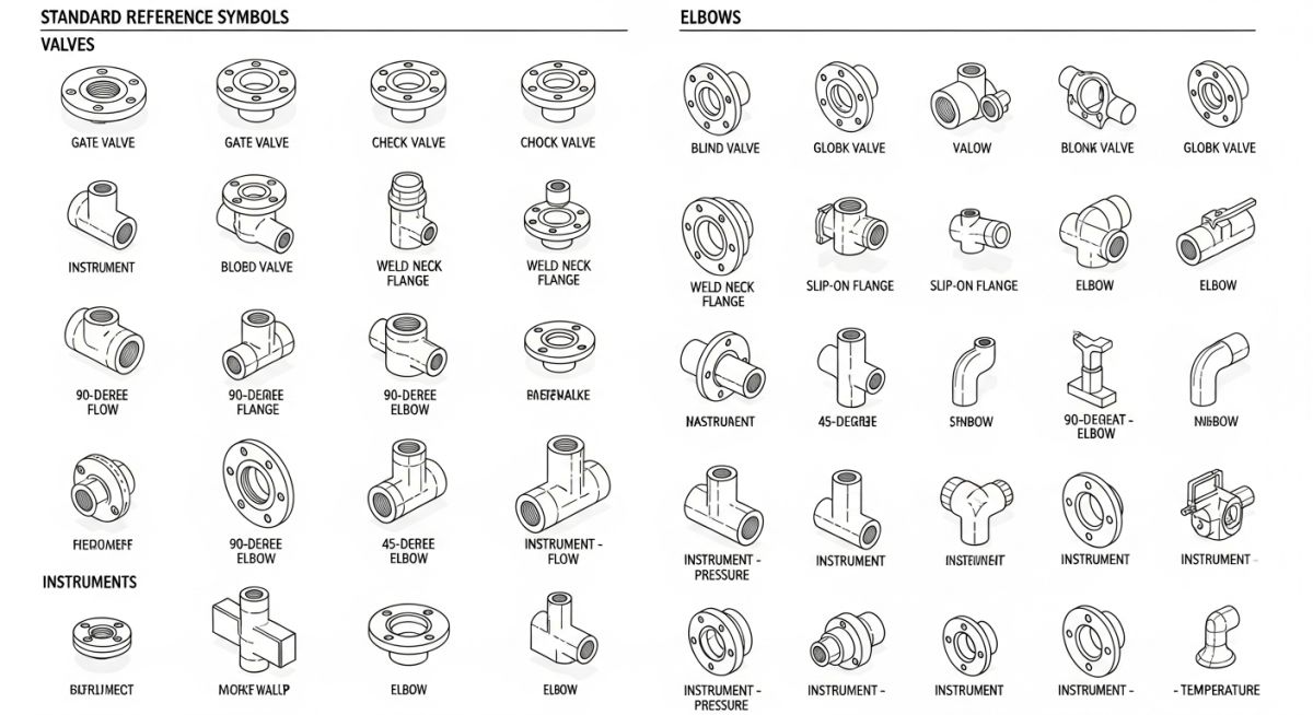
| Component | Isometric Symbol Description | Connection Type | Standard Reference |
|---|---|---|---|
| Gate Valve | Two triangles pointing at each other with a vertical line in the center. | Flanged / Butt-Weld | ASME B16.10 |
| Concentric Reducer | A trapezoidal shape showing a uniform decrease in pipe diameter. | Butt-Weld | ASME B16.9 |
| Eccentric Reducer | A trapezoidal shape with one flat side, indicating flat-on-bottom (FOB) or flat-on-top (FOT). | Butt-Weld | ASME B16.9 |
| Flange (Weld Neck) | A thick vertical line perpendicular to the pipe run with a hub representation. | Welded / Bolted | ASME B16.5 |
| Acronym / Parameter | Full Technical Name | Physical Meaning & Application | Governing Standard |
|---|---|---|---|
| BOM | Bill of Materials | A complete list of components, quantities, sizes, and material grades required for fabrication. | ASME Y14.34 |
| TOC | Top of Concrete | Reference elevation for structural foundations supporting piping sleepers or pipe racks. | ASCE 7 |
| BOP | Bottom of Pipe | The lowest external elevation of the pipe shell, critical for calculating clearance and support heights. | ASME B31.3 |
| FOB | Flat on Bottom | Orientation of eccentric reducers to prevent liquid pockets in horizontal lines. | ASME B31.3 |
Verifying Piping Isometric Drawings on Site
Before releasing any isometric drawing to the fabrication shop, a physical walkdown of the piping route is necessary. This step ensures that the theoretical dimensions generated by the design software align with the physical realities of the plant.
-
Verify Tie-In Coordinates: Cross-reference the coordinates of existing equipment nozzles or piping headers with the isometric drawing. -
Confirm Structural Clearances: Ensure the pipe path does not clash with structural steel, cable trays, or HVAC ducting. -
Check Valve Stem Orientation: Confirm that valve handwheels have sufficient clearance for operation and maintenance access under OSHA standards. -
Validate Support Locations: Ensure that structural steel is available at the exact locations specified for pipe supports. -
Identify Field Weld Locations: Confirm that field welds are placed in accessible locations for the welding rig and non-destructive testing (NDT) technicians.
Field Case Study: Real-World Application
During the construction of a high-pressure steam line in a power plant expansion, the field crew reported that a pre-fabricated 8-inch spool was 150 mm too short to reach the turbine inlet nozzle. The isometric drawing had been generated directly from a 3D model, but the turbine foundation had settled by 50 mm, and the turbine nozzle itself was manufactured with a slight dimensional deviation from the vendor drawing.
I was called to the site to resolve the issue. We had to scrap the pre-fabricated spool, which cost the project 12,000 in materials and labor, and delay the steam blow-down sequence by four days. To fix the issue, we took actual field measurements of the turbine nozzle coordinates, updated the isometric drawing, added a 150 mm field weld allowance to the new spool, and fabricated it on-site.
My Recommendation: Never trust vendor drawings for critical equipment connections. Always perform a physical site measurement of equipment nozzle coordinates after the equipment is set on its final foundation, and update your piping isometric drawings before releasing the spools for shop fabrication.
Frequently Asked Engineering Questions
What is the difference between a P&ID and a Piping Isometric Drawing?
Why are isometric drawings drawn at a 30-degree angle?
What is a “spool” in a piping isometric drawing?
How do you represent a slope on an isometric drawing?
Which software is best for generating piping isometric drawings?
What is the significance of the “Bill of Materials” on an isometric?
Complete Course on
Piping Engineering
Check Now
Key Features
- 125+ Hours Content
- 500+ Recorded Lectures
- 20+ Years Exp.
- Lifetime Access
Coverage
- Codes & Standards
- Layouts & Design
- Material Eng.
- Stress Analysis

📚 Recommended Resources: piping isometric drawings
Read these Guides
🎓 Advanced Training


Related posts:
![Super duplex stainless steel piping network on an offshore oil drilling platform.]()
Super Duplex Stainless Steel Oil and Gas Piping Design Guide
![Industrial duplex stainless steel piping system in a chemical processing facility.]()
Understanding Duplex Stainless Steel Properties and Industrial Piping Applications
![A welder performing a critical golden joint weld on an industrial steel pipeline.]()
What is a Golden Joint in Piping Systems?
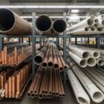
![A collection of different types of industrial pipes classified by material and size on a storage rack.]()
Comprehensive Guide to Types of Pipes and Industrial Classification Systems
![Industrial piping network with digital overlays representing inch-dia and inch-meter engineering calculations.]()
What are Inch-Dia and Inch-Meter in Piping Systems?
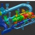
![3D finite element stress analysis model of an industrial piping system showing stress distribution.]()
What Causes Piping System Stresses in Industrial Plants?