Table of Contents
Piping Fasteners: Engineering Selection, Torque Calculations, and Installation Standards
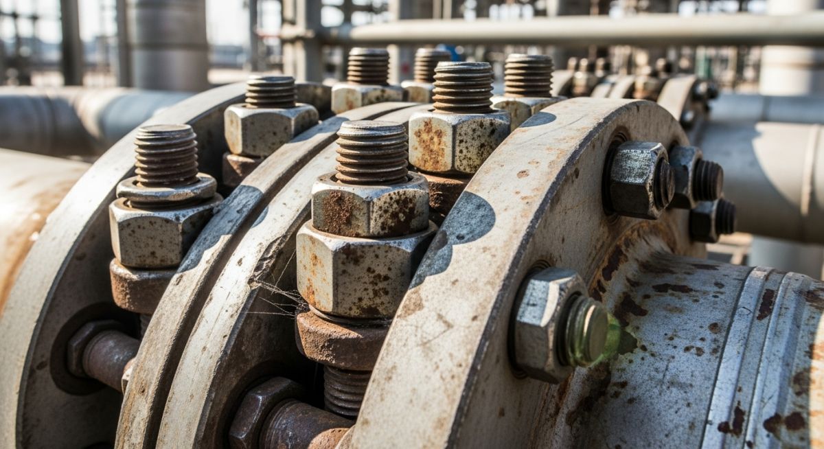
In my 20+ years of active piping engineering on refinery and petrochemical projects, I have seen many field failures. Most of these did not stem from pipe wall thinning or valve body ruptures. Instead, they occurred at the bolted flange joint. The selection of your piping fasteners is not a minor detail to be left to chance or delegated without strict oversight. It is a core design decision that directly impacts the pressure-containing capability of your entire system.
When we design under ASME B31.3 Process Piping, we treat the flange, the gasket, and the fasteners as an integrated structural system. If any one of these three elements is incorrectly specified or poorly installed, the joint will fail during hydrotesting or, worse, during hot operation. Let us dive deep into the engineering principles that govern these critical components.
Key Engineering Takeaways
- Stud bolts are preferred over machine bolts for all high-pressure and high-temperature services due to uniform stress distribution.
- ASTM A193 Grade B7 is the workhorse alloy steel for medium-to-high temperature services, while ASTM A320 Grade L7 is required for low-temperature applications.
- Controlled torque application using a calibrated wrench is the only reliable method to achieve the target bolt preload without yielding the fastener.
- The nut factor (K) is highly sensitive to lubrication; unlubricated threads can cause up to a 50% loss in effective bolt preload.
How to Select Piping Fasteners for High-Pressure Systems
Piping Fasteners Selection: The process of choosing appropriate bolting materials, grades, and dimensions based on operating temperature, pressure, and fluid compatibility in compliance with ASME B31.3. This engineering step ensures that the joint remains within allowable stress limits during thermal cycles.
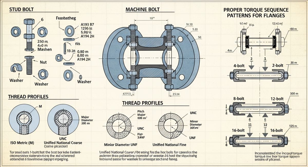
In industrial piping, we primarily choose between two types of fasteners: stud bolts and machine bolts. In my practice, I do not permit machine bolts for any process piping above Class 150 or temperatures exceeding 200°C. A stud bolt, which is a threaded rod with nuts on both ends, offers a major mechanical advantage. The tensile stress is distributed symmetrically along the entire length of the stud. Conversely, a machine bolt has an integral head on one side, which introduces a stress concentration point at the head-to-shack transition.
The Mechanics of Bolt Preload and Torque Calculations
To achieve a leak-tight seal, the fasteners must exert sufficient compressive force on the gasket to flow it into the flange serrations. This force is called the bolt preload. If the preload is too low, internal pressure will blow past the gasket. If it is too high, you risk crushing the gasket or yielding the bolts.
The relationship between applied torque and the resulting bolt tension is calculated using the standard torque-tension equation:
Where:
T = Target torque (ft-lbs)
K = Nut factor (dimensionless friction coefficient)
D = Nominal bolt diameter (inches)
F = Target bolt tension or preload (pounds)
Practical Engineering Calculation Example:
Let us calculate the required torque for an 8-inch Class 300 flange joint using ASTM A193 Grade B7 stud bolts (7/8-inch diameter, 9 UNC threads).
- Determine Yield Strength: ASTM A193 B7 has a minimum yield strength of 105,000 psi for diameters under 2.5 inches.
- Target Stress: We typically target 50% of the yield strength for assembly preload to allow a safety margin for thermal expansion. Target Stress = 52,500 psi.
- Calculate Tensile Stress Area (As): For a 7/8-inch UNC bolt, the tensile stress area is 0.462 square inches.
- Calculate Target Tension (F): F = Stress * As = 52,500 psi * 0.462 sq in = 24,255 lbs.
- Select Nut Factor (K): With a high-quality copper-based anti-seize lubricant, K is approximately 0.15. (Unlubricated steel-on-steel can exceed 0.20).
- Calculate Torque (T): T = (0.15 * 0.875 inches * 24,255 lbs) / 12 = 265.3 ft-lbs.
Never allow your field crew to tighten fasteners dry. If a technician applies the calculated 265 ft-lbs of torque to a dry, rusty stud (where K can rise to 0.25), the actual preload tension achieved will drop to around 14,500 lbs. This is a 40% reduction in gasket seating force, which will almost certainly cause a joint leak during the system hydrotest.
Code Compliance and Standards
All bolting materials must comply with ASME B16.5 for flanges up to 24 inches, and ASME B16.47 for larger sizes. The dimensions of heavy hex nuts must conform to ASME B18.2.2, which provides a larger width across flats than standard nuts to distribute the heavy clamping loads safely.
Material Specifications for Piping Fasteners and Bolting
Bolting Material Specifications: The standardized physical and chemical properties of fasteners defined by ASTM and ASME codes to guarantee mechanical integrity. These specifications dictate the temperature limits, tensile strength, and yield strength of bolts used in pressurized joints.
Selecting the correct material grade is a safety-critical step. Below is the engineering reference table I use during the design phase to match bolting materials with process operating temperatures.
| ASTM Bolt Grade | Material Type | Service Temp Range | Min Yield Strength (ksi) | Matching Nut Grade |
|---|---|---|---|---|
| ASTM A193 Gr. B7 | Chromium-Molybdenum Alloy Steel | -30°C to 425°C | 105 | ASTM A194 Gr. 2H |
| ASTM A193 Gr. B16 | Chromium-Molybdenum-Vanadium | -30°C to 525°C | 105 | ASTM A194 Gr. 4 or 7 |
| ASTM A193 Gr. B8 Cl. 2 | AISI 304 Stainless Steel (Strain Hardened) | -196°C to 538°C | 75 | ASTM A194 Gr. 8 |
| ASTM A320 Gr. L7 | Alloy Steel (Low-Temp Impact Tested) | -101°C to 343°C | 105 | ASTM A194 Gr. 7 or 7L |
Technical Mapping & Specifications Matrix
To ensure complete traceability and compliance across international standards, use this mapping matrix for procurement and quality assurance.
| Standard / Acronym | Technical Definition | Primary Application | Hyperlinked Reference |
|---|---|---|---|
| ASME B16.5 | Pipe Flanges and Flanged Fittings (NPS 1/2 through NPS 24) | Governs bolt circle diameters, bolt hole sizes, and flange dimensions. | ASME Portal |
| ASTM A193 | Standard Specification for Alloy-Steel and Stainless Steel Bolting | Defines chemical and mechanical properties for high-temperature service. | ASTM Portal |
| Nut Factor (K) | Friction coefficient factor representing thread and face resistance | Used in torque-to-tension conversion calculations. | Engineering Parameter |
Field Installation Checklist for Bolted Joints
Bolted Joint Installation Checklist: A systematic field verification protocol designed to ensure correct alignment, lubrication, and torque application during flange assembly. This quality control measure prevents uneven gasket compression and subsequent joint failure.
During my time managing construction sites, I established a strict rule: no flange is to be closed without a signed-off inspection checklist. Below is the exact protocol that must be followed by the mechanical crew before and during the tightening process.
Pre-Assembly and Tightening Verification Protocol
-
Flange Alignment Check: Verify that flange faces are parallel within 0.5 mm and bolt holes align within 1.5 mm. Never use the bolts to pull misaligned piping into place.
-
Fastener Inspection: Confirm that the stud bolt grade (e.g., B7) and nut grade (e.g., 2H) match the piping specification. Check for thread damage or corrosion.
-
Gasket Verification: Ensure the gasket is clean, dry, and free of defects. Never reuse a gasket.
-
Lubrication Application: Apply a uniform coat of approved anti-seize lubricant to the stud threads and the nut bearing faces. Do not lubricate the gasket.
-
Star Pattern Tightening: Tighten bolts in a cross-pattern (star pattern) in four distinct stages: Hand tight, 30% torque, 60% torque, and 100% of the target torque.
-
Final Rotational Pass: Perform a final clockwise rotational pass at 100% torque to ensure all bolts are uniformly loaded.
Field Case Study: Real-World Application
Flange Leak Case Study: An analysis of a high-pressure steam line failure caused by improper fastener selection and uneven torque distribution. The investigation and subsequent remediation demonstrate the critical nature of controlled bolting procedures.
The Problem: Persistent Leaks on a Class 600 Steam Line
During the commissioning of a medium-pressure steam line (operating at 42 bar and 380°C), a critical flange joint downstream of a pressure-reducing station began leaking steam. The field crew attempted to stop the leak by hot-tightening the bolts with an impact wrench. This action stripped the threads on two bolts, worsening the leak and forcing an emergency shutdown of the steam header.
The Investigation & Engineering Outcome
I led the root cause analysis. We discovered two major errors:
- The warehouse had issued standard carbon steel machine bolts (ASTM A307) instead of the specified ASTM A193 Grade B7 alloy steel studs. The A307 bolts had yielded under the high operating temperature.
- The maintenance crew had used manual impact wrenches with no torque control, resulting in highly uneven bolt loads across the flange face.
Remediation: We replaced all fasteners with genuine ASTM A193 Grade B7 studs and ASTM A194 Grade 2H heavy hex nuts. We calculated the target torque (310 ft-lbs) and applied it using a calibrated hydraulic torque wrench in a strict 4-stage star pattern. The line was restarted, and the joint has remained completely leak-free for over five years of continuous operation.
This case highlights why we must treat piping fasteners as engineered components. A simple substitution of a bolt grade can lead to catastrophic failures, production losses, and severe safety hazards.
Frequently Asked Engineering Questions
What is the difference between a stud bolt and a machine bolt in piping?
Why is ASTM A193 Grade B7 the industry standard for piping fasteners?
How does the “Nut Factor” (K) affect torque calculations?
What is the correct bolt tightening sequence for a flange?
Can we reuse stud bolts after they have been torqued?
How does temperature affect the allowable stress of piping fasteners?
Complete Course on
Piping Engineering
Check Now
Key Features
- 125+ Hours Content
- 500+ Recorded Lectures
- 20+ Years Exp.
- Lifetime Access
Coverage
- Codes & Standards
- Layouts & Design
- Material Eng.
- Stress Analysis

📚 Recommended Resources: Piping Fasteners
Read these Guides


Related posts:
![Industrial metallic piping network with stainless steel pipes and valves in a processing plant.]()
What is Metallic Piping: Types, Advantages, Applications, and ASTM Standards
![Industrial gas processing facility comparing cryogenic LNG storage tanks and pressurized LPG bullet tanks.]()
What are the Differences Between LNG and LPG?
![Split-screen comparison of liquid oil failing under extreme heat versus dry graphite lubricating a mechanical bearing smoothly.]()
Why Is Graphite a Better Lubricant Than Oil in Industrial Piping?
![Tall industrial distillation column tower at a chemical processing plant]()
What is a Distillation Column? Working Principles and Types
![Close-up of various metal pipe fittings with different thread types on an engineering blueprint.]()
Understanding the Different Types of Pipe Threads in Piping Systems
![A collection of different metal and plastic pipe ferrules resting on an engineering blueprint.]()
How Do Pipe Ferrules Ensure Leak-Free Industrial Piping Systems?