Widely Used Piping Codes and Standards for Industrial Safety
In my two decades of experience navigating complex brownfield and greenfield projects, I have learned that the difference between a successful commissioning and a catastrophic failure often boils down to the rigorous application of widely used piping codes and standards. Engineers frequently mistake “standards” for “suggestions,” but in the high-pressure environments of oil, gas, and chemical processing, these documents are the bedrock of our professional liability and public safety.
Whether you are designing a cryogenic transfer line or a high-temperature steam header, the selection of the correct code—be it ASME B31.3 for process piping or ASME B31.1 for power piping—dictates your wall thickness calculations, material selection, and weld inspection requirements. This guide serves as your technical roadmap to navigating these regulatory frameworks effectively.
Key Takeaways for Piping Engineers
- Master the jurisdictional boundaries between ASME B31.1, B31.3, and B31.4.
- Understand how API standards complement ASME codes for specific equipment interfaces.
- Learn to apply material specifications from ASTM to satisfy code-required pressure-temperature ratings.
- Recognize the critical role of non-destructive examination (NDE) as defined by code-specific acceptance criteria.
Technical Analysis of Widely Used Piping Codes and Standards
Piping Code Application: The systematic selection and implementation of ASME and API standards to govern the design, fabrication, and inspection of pressure-containing piping components within specific industrial service environments.
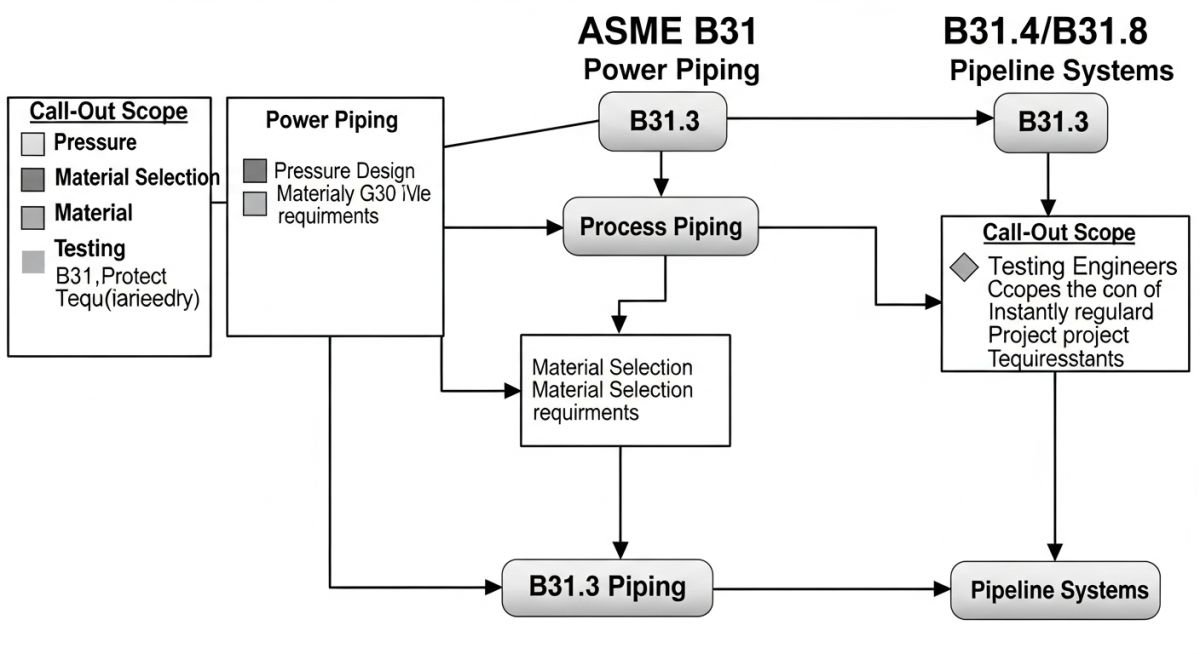
When I approach a new piping design, the first step is always defining the “Code of Record.” The ASME B31 series is the global benchmark for pressure piping. For process plants, ASME B31.3 is the primary authority. It covers everything from the fluid service category—ranging from Category D (non-toxic, non-flammable) to High Pressure (HP) and High Purity—to the specific stress intensification factors (SIF) required for fatigue analysis.
The design pressure and temperature limits are governed by the pressure-temperature ratings found in ASME B16.5 (for flanges) and B16.34 (for valves). A common error I see in junior engineers is failing to account for the “allowable stress” values (S) which are temperature-dependent. These values are extracted from the ASME Boiler and Pressure Vessel Code (BPVC) Section II, Part D. If your operating temperature exceeds the creep range of the material, you must apply the time-dependent allowable stress values, which are significantly lower than the room-temperature yield strength.
Field Warning: Material Compatibility
Never assume that a material listed in an ASTM specification is automatically “code-approved” for your specific ASME B31.3 service. You must verify that the material is explicitly listed in the “Allowable Stresses” tables of the code. Using an unlisted material requires a formal “Unlisted Material” qualification process, which involves extensive testing and documentation that can delay project timelines by months.
For stress analysis, we utilize the flexibility analysis methods outlined in B31.3. The displacement stress range (S_E) must satisfy the equation: S_E = i * M_c / Z, where ‘i’ is the stress intensification factor, ‘M_c’ is the resultant moment, and ‘Z’ is the section modulus. If the calculated stress exceeds the allowable displacement stress range (S_A), we must introduce expansion loops or change the routing to increase system flexibility.
API standards, such as API 5L for line pipe and API 600 for steel gate valves, provide the manufacturing and testing requirements that ASME codes reference. While ASME tells you how to design the system, API tells you how to build the components that make up that system. Ignoring the synergy between these two bodies of work leads to procurement mismatches, where a valve might meet the pressure rating but fail the face-to-face dimension requirements or the material toughness testing required for low-temperature service.
Standardized Engineering Framework: The utilization of established piping codes provides a predictable, legally defensible, and technically sound methodology for ensuring the safety and reliability of industrial pressure systems.
Advantages
- Provides a globally recognized safety baseline for insurance and regulatory compliance.
- Reduces design iteration time by offering pre-validated stress intensification factors.
- Ensures interoperability between components from different global manufacturers.
- Simplifies the procurement process through standardized material and dimension specifications.
- Facilitates easier maintenance and replacement due to uniform flange and fitting standards.
Disadvantages
- Rigid adherence can lead to over-engineering and increased capital expenditure.
- Updates to codes often lag behind rapid advancements in material science.
- Requires significant expertise to interpret complex, often overlapping code requirements.
- Compliance documentation creates a heavy administrative burden for small-scale projects.
- Can stifle innovation in non-traditional piping configurations or novel materials.
Industrial Piping Implementation: The practical application of ASME and API standards across diverse sectors to manage fluid transport, pressure containment, and thermal expansion in critical infrastructure.
High-Pressure Hydrocarbon Processing
In refinery operations, ASME B31.3 governs the design of high-pressure piping systems that handle volatile hydrocarbons. Engineers must strictly adhere to the code’s requirements for weld joint quality and heat treatment to prevent brittle fracture and stress corrosion cracking in sour service environments.
Power Generation Steam Headers
Power plants rely on ASME B31.1 for the design of high-temperature, high-pressure steam piping. This application requires rigorous creep analysis and the use of specialized alloy steels, such as P91, which must be welded and inspected according to strict code-mandated procedures to ensure long-term structural integrity.
Cryogenic Liquefied Natural Gas (LNG) Facilities
LNG piping systems operate at temperatures as low as minus 162 degrees Celsius, necessitating the use of materials like 9% nickel steel or stainless steel. The design must account for extreme thermal contraction and the potential for ice formation, with all components selected based on their low-temperature impact toughness as defined by ASME and ASTM standards.
Selecting the correct piping component requires a rigorous understanding of pressure-temperature (P-T) ratings as defined by ASME B16.5 and ASME B16.34. These standards provide the baseline for flange and valve integrity, ensuring that materials maintain structural stability under extreme thermal and mechanical loads. In my experience, engineers often overlook the non-linear degradation of material strength as temperatures rise, leading to premature gasket failure or flange leakage.
The following table summarizes the relationship between nominal pressure classes and material group limitations. Always verify the specific material specification against the latest edition of the code, as allowable stress values are subject to periodic updates based on metallurgical research and failure analysis data. When designing for high-pressure steam or cryogenic service, these ratings serve as the primary gatekeeper for safety and compliance.
| Class Rating | Material Group | Max Temp (F) | Primary Standard |
|---|---|---|---|
| 150 | Carbon Steel (A105) | 750 | ASME B16.5 |
| 300 | Carbon Steel (A105) | 800 | ASME B16.5 |
| 600 | Stainless (F316) | 1000 | ASME B16.34 |
Remember that these ratings are strictly for pressure-containing components. External loads, such as thermal expansion forces or seismic events, must be calculated separately using ASME B31.3 stress analysis methods to ensure the total equivalent stress does not exceed the allowable limits of the piping system.
The following matrix maps critical piping entities to their governing standards and physical parameters. This cross-reference tool is vital for junior and senior engineers alike to ensure that every component—from a simple bolt to a complex control valve—is specified according to the correct industrial code. Misalignment between these entities is a leading cause of procurement delays and site-level safety incidents.
By maintaining this mapping, you ensure that your design documentation remains audit-ready and compliant with international safety regulations. Note that while these standards provide the baseline, local jurisdictional requirements may impose additional constraints that must be integrated into your project-specific piping specifications.
| Entity | Governing Code | Key Parameter |
|---|---|---|
| Process Piping | ASME B31.3 | Allowable Stress |
| Pipeline Systems | ASME B31.4 | Hoop Stress |
| Valves | API 6D | Seat Leakage |
Verification of piping systems during the construction phase is the final line of defense against catastrophic failure. My experience in field engineering has taught me that even the most robust design can fail if the installation does not strictly adhere to the governing codes. This checklist serves as a mandatory guide for site inspectors and quality control teams to ensure that every weld, support, and component meets the required ASME and API standards.
-
[ ]
Material Traceability: Confirm all pipe spools and fittings match the Material Test Reports (MTRs) and are marked with the correct ASTM grade. -
[ ]
Weld Integrity: Verify that all welding procedures (WPS) are qualified per ASME Section IX and that NDT reports are signed off. -
[ ]
Support Alignment: Ensure that spring hangers and rigid supports are installed per the stress analysis report to prevent excessive nozzle loading. -
[ ]
Pressure Testing: Validate that the hydrostatic test pressure is calculated correctly and that the gauge calibration is current. -
[ ]
Bolt Torque: Confirm that flange bolting is tightened to the specified torque values using calibrated tools to ensure gasket seating.
Before commissioning, ensure that all non-conformances are closed out and documented in the final turnover package. A piping system is only as strong as its weakest connection; therefore, rigorous adherence to these verification steps is non-negotiable for long-term operational safety.
The Problem: Premature Flange Leakage in High-Temperature Service
A refinery experienced recurring flange leaks in a high-temperature hydrocarbon line, leading to significant downtime and safety risks.
- Incorrect gasket selection for the thermal cycling profile.
- Inadequate bolt tensioning procedures during initial installation.
- Failure to account for differential thermal expansion between the flange and the pipe.
- Lack of adherence to ASME B16.5 bolt-up requirements.
The Outcome: Successful Remediation and Code Compliance
By implementing a revised piping integrity program, the facility eliminated the leaks and improved overall system reliability.
- Transitioned to spiral-wound gaskets with inner rings for better thermal stability.
- Implemented a strict hydraulic torque-tightening procedure with documented verification.
- Updated the piping specification to include high-strength bolting materials.
- Achieved 100% leak-free performance during the subsequent two-year operational cycle.
Recommendation: Always perform a root cause analysis on recurring leaks, focusing on the intersection of material selection, installation technique, and the specific requirements of the governing piping code.
How do I choose between ASME B31.3 and B31.1?
The selection depends primarily on the service application and the facility type. ASME B31.1 is specifically designed for power piping systems, such as those found in steam-electric generating stations and district heating systems, where safety and reliability are paramount for public utility infrastructure.
- Use B31.1 for boiler external piping and power plant auxiliary systems.
- Use B31.3 for process piping in refineries, chemical plants, and pharmaceutical facilities.
- B31.3 offers more flexibility for complex chemical processes but requires more rigorous stress analysis.
- Always check local jurisdictional requirements, as some states mandate B31.1 for all high-pressure steam systems regardless of the facility type.
What is the significance of the API 6D standard?
API 6D is the global benchmark for pipeline valves, covering design, manufacturing, and testing requirements for ball, check, gate, and plug valves. It ensures that valves used in critical pipeline infrastructure can withstand the high-pressure, long-distance transport of hydrocarbons.
- It mandates specific pressure-temperature ratings that align with ASME B16.34.
- It defines rigorous testing protocols, including shell and seat leakage tests.
- It is essential for ensuring interoperability between different valve manufacturers in a pipeline project.
- Compliance with API 6D is often a contractual requirement for major oil and gas pipeline operators.
How does ASTM material selection impact piping safety?
ASTM standards define the chemical composition and mechanical properties of the materials used in piping. Selecting the wrong ASTM grade can lead to brittle fracture, corrosion, or failure under thermal stress.
- ASTM A106 is the standard for seamless carbon steel pipe for high-temperature service.
- ASTM A312 covers seamless and welded austenitic stainless steel pipes.
- Material selection must account for the fluid’s corrosivity and the operating temperature range.
- Always verify that the chosen ASTM material is listed as an “allowable material” in the applicable ASME B31 code section.
What are the requirements for hydrostatic testing?
Hydrostatic testing is the primary method for verifying the pressure integrity of a newly installed piping system. ASME B31.3 requires a test pressure of at least 1.5 times the design pressure, adjusted for temperature.
- The test fluid must be compatible with the piping material to prevent internal corrosion.
- All temporary supports must be installed to handle the weight of the test water.
- The system must be vented to ensure all air is removed before pressurization.
- Safety zones must be established around the piping during the test to protect personnel in case of a component failure.
How do I manage thermal expansion in piping?
Thermal expansion is a critical design factor that, if ignored, leads to pipe buckling or nozzle failure. Engineers use expansion loops, bellows, and flexible supports to absorb the movement caused by temperature changes.
- Calculate the total thermal growth based on the temperature differential and material coefficient of expansion.
- Use stress analysis software to model the system and identify high-stress points.
- Ensure that anchors and guides are placed correctly to direct the expansion into the loops.
- Verify that the piping system remains within the allowable stress range defined by ASME B31.3.
What is the role of NDT in piping codes?
Non-Destructive Testing (NDT) is essential for verifying the quality of welds and base materials without damaging the piping system. ASME B31.3 specifies the required extent of NDT based on the service category and fluid hazard level.
- Radiographic Testing (RT) is commonly used to detect internal weld defects like porosity or slag.
- Ultrasonic Testing (UT) is effective for measuring wall thickness and detecting laminar flaws.
- Dye Penetrant (PT) and Magnetic Particle (MT) testing are used for surface-breaking defect detection.
- All NDT personnel must be qualified to recognized standards like ASNT to ensure the reliability of the inspection results.
📚 Recommended Resources: Piping Codes and Standards
Read these Guides
🎓 Advanced Training


Complete Course on
Piping Engineering
Check Now
Key Features
- 125+ Hours Content
- 500+ Recorded Lectures
- 20+ Years Exp.
- Lifetime Access
Coverage
- Codes & Standards
- Layouts & Design
- Material Eng.
- Stress Analysis
