Mastering Piping Abbreviations and Common Piping Terms in Engineering Design
In my 20-plus years of walking the gravel paths of petrochemical refineries and redlining isometric drawings in engineering offices, I have seen minor misunderstandings lead to multi-million dollar field reworks. A simple mix-up between “TOC” (Top of Concrete) and “TOS” (Top of Steel), or misinterpreting “NPS” as Nominal Pipe Size when the designer meant Nominal Pipe Stiffness, can halt a crane lift in its tracks. Piping drawings are dense, highly compressed maps of physical reality. To navigate them without error, you must master the shorthand language of the industry.
Every line, valve, instrument, and support on a Piping and Instrumentation Diagram (P&ID) or isometric sheet relies on standardized abbreviations. These terms are not just arbitrary shortcuts; they are governed by international standards such as ASME Y14.38. When you are in the field coordinating with fabricators, pipefitters, and quality control inspectors, speaking this exact language is your primary shield against construction errors.
Key Takeaways for Piping Professionals
- Understand the structural difference between elevation markers like BOP, TOS, and COG.
- Learn how material designations like CS, SS, and alloy abbreviations dictate welding procedures.
- Master the connection types including BW, SW, NPT, and RF to prevent flange mismatches.
- Discover how to cross-reference drawing abbreviations with the master project legend.
- Recognize the safety-critical abbreviations used for pressure relief and isolation systems.
Why Do We Use Piping Abbreviations in Design?
In the high-pressure world of industrial piping design, space on a drawing sheet is premium real estate. If we wrote out “Raised Face Slip-On Carbon Steel Flange Class 150” every time we placed one, our drawings would be illegible webs of text. Instead, we write “RF SO FLG CS 150#”. This compression of data allows engineers to focus on spatial routing, stress analysis, and system integrity while keeping the drawing clean and readable.
When performing stress analysis in software like CAESAR II, or calculating minimum wall thickness under ASME B31.3, abbreviations define our input parameters. For instance, the pressure design thickness calculation relies on variables that are directly tied to drawing abbreviations:
t = (P * D) / (2 * (S * E * W + P * Y))
Where:
t = Pressure design thickness (linked to WT on drawings)
P = Internal design gage pressure (linked to DP in line lists)
D = Outside diameter of pipe (determined by NPS)
S = Allowable stress value for material (linked to CS, SS, or AS designations)
E = Quality factor (determined by weld type: ERW, SMLS, etc.)
W = Weld joint strength reduction factor
Y = Coefficient from ASME B31.3 Table 304.1.1
If a designer misinterprets “SMLS” (Seamless) as “ERW” (Electric Resistance Welded), they might use an incorrect joint quality factor (E = 0.85 instead of 1.00). This error artificially increases the required wall thickness, driving up material costs and altering the system’s flexibility during thermal expansion.
Thermal expansion is another area where abbreviations dictate physical design. When routing high-temperature lines, we use “EJ” (Expansion Joint), “GUIDE” (Pipe Guide), and “ANC” (Anchor) to control pipe movement. Misinterpreting a guide for an anchor on an isometric drawing can restrict thermal growth, leading to catastrophic flange leakage or structural buckling of the pipe rack.
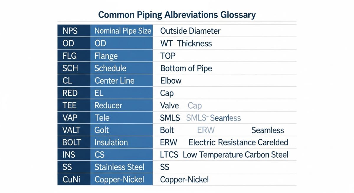
Below is a comprehensive reference table detailing the most common abbreviations used in piping engineering, design, and field construction. These terms conform to standard industry practices and ASME Y14.38 guidelines.
| Abbreviation | Full Term | Category | Engineering Application |
|---|---|---|---|
| BOP | Bottom of Pipe | Elevation | Used to establish support steel heights and ensure gravity drainage. |
| TOS | Top of Steel | Elevation | Defines the upper surface of structural steel supporting the pipe. |
| FOB | Flat on Bottom | Fitting Orientation | Specifies eccentric reducer orientation to prevent liquid pooling. |
| FOT | Flat on Top | Fitting Orientation | Specifies eccentric reducer orientation to prevent vapor pockets in pump suctions. |
| BW | Butt Weld | Connection Type | High-strength welded joint used for piping 2 inches and larger. |
| SW | Socket Weld | Connection Type | Used for small-bore piping (1.5 inches and smaller) in non-corrosive service. |
| RF | Raised Face | Flange Facing | Concentrates sealing pressure on a small area; most common flange type. |
| RTJ | Ring Type Joint | Flange Facing | High-pressure, high-temperature metallic ring seal used in critical services. |
| NPS | Nominal Pipe Size | Dimension | Standard North American designation for pipe diameters. |
| DN | Diameter Nominal | Dimension | Metric equivalent of NPS, measured in millimeters. |
This matrix maps core technical entities, structural acronyms, and physical parameters to their governing standards and design impacts.
| Entity / Acronym | Physical Parameter | Governing Standard | Design Impact & Stress Considerations |
|---|---|---|---|
| CS (Carbon Steel) | Material Grade (e.g., A106-B) | ASTM A106 | Determines allowable stress limits up to 425 degrees Celsius. Subject to oxidation. |
| SS (Stainless Steel) | Material Grade (e.g., A312-TP316) | ASTM A312 | High corrosion resistance. Requires careful thermal expansion analysis due to high expansion coefficient. |
| SCH (Schedule) | Wall Thickness (WT) | ASME B36.10M | Directly impacts pressure containment capability and structural stiffness of the span. |
| Rating (150#, 300#) | Pressure-Temperature Class | ASME B16.5 | Defines maximum allowable working pressure at specific operating temperatures. |
Field Verification of Piping Abbreviations
Before signing off on a piping system for hydrostatic testing, you must perform a physical walkdown. This checklist ensures that the abbreviations stamped on the physical components match the engineering design documents exactly.
Piping Drawing vs. Field Installation Checklist
-
Verify BOP (Bottom of Pipe) Elevations: Check that the physical pipe support heights match the BOP elevations specified on the isometric drawings. This is critical for lines with a designated slope (e.g., 1:100 slope for steam condensate lines).
-
Confirm Reducer Orientations (FOB vs. FOT): Inspect all eccentric reducers. Ensure pump suction lines use FOT (Flat on Top) to prevent vapor pockets, and horizontal process lines use FOB (Flat on Bottom) to allow complete drainage.
-
Match Flange Ratings (ASME B16.5): Check the physical stamp on all flanges (e.g., “150#”, “300#”, “600#”). Verify that they match the rating abbreviation on the isometric drawing. Mixing up a 150# flange with a 300# flange in a high-pressure system will cause catastrophic joint failure.
-
Validate Material Stamps (CS vs. SS): Physically inspect the material heat numbers and grade stamps on the pipe body and fittings. Ensure ASTM A106 (CS) is not substituted where ASTM A312 TP316 (SS) is specified.
-
Inspect Valve Flow Direction (Flow Arrow): Verify that check valves (CV) and globe valves (GLV) are installed in the correct flow direction as indicated by the flow arrow abbreviation on the P&ID.
Field Case Study: Real-World Application
The Problem: The Costly BOP vs. TOS Misinterpretation
During the construction of a major refinery expansion in 2024, a structural steel fabricator and a piping installation contractor misinterpreted drawing elevations on a 24-inch flare header. The isometric drawing specified a “BOP” (Bottom of Pipe) elevation of 104.500 meters. However, the structural steel drawing showed a “TOS” (Top of Steel) elevation of 104.500 meters.
Because the piping contractor assumed the pipe should rest directly on the steel without verifying the 100mm wear pad thickness, they installed the line too low. This eliminated the required 1:200 slope of the flare line, causing heavy hydrocarbons to pool in the low spots, creating a severe safety hazard during process upsets.
The Outcome: Engineering Resolution & Prevention
The error was caught during the pre-commissioning walkdown. To resolve the issue, we had to modify 12 structural steel pipe shoes and re-weld the support assemblies to restore the correct slope. This rework cost the project 85,000 in direct labor and delayed the system pressure test by two weeks.
To prevent this from happening again, we updated the project’s engineering execution plan to mandate a joint review of all interface elevations (BOP, TOS, and TOC) between the structural and piping disciplines before releasing drawings for construction.
My direct recommendation to all young piping engineers is simple: always verify the reference datum. When you see an elevation abbreviation on an isometric drawing, trace it back to the civil benchmark to ensure your physical supports match the design intent.
Frequently Asked Engineering Questions
What is the difference between BOP and TOS in piping design?
Why is the abbreviation FOB critical for eccentric reducers?
What does RTJ stand for, and when should it be used?
How do NPS and DN differ on international projects?
What is the difference between BW and SW connections?
Where can I find the master list of approved piping abbreviations?
===FAQ_BLOCK===
Complete Course on
Piping Engineering
Check Now
Key Features
- 125+ Hours Content
- 500+ Recorded Lectures
- 20+ Years Exp.
- Lifetime Access
Coverage
- Codes & Standards
- Layouts & Design
- Material Eng.
- Stress Analysis



