Overview of Lateral Buckling and Upheaval Buckling of Pipelines
In my 20 years of managing subsea pipeline integrity, I have watched the industry push operating limits to extreme boundaries. As offshore fields trend toward deeper waters and higher temperatures, managing the physical forces within subsea pipelines becomes a major engineering challenge. When a pipeline carries high-temperature, high-pressure (HPHT) fluids, it naturally wants to expand. However, because it is restrained by the surrounding soil or seabed friction, it cannot expand freely. This restraint builds up massive axial compressive forces.
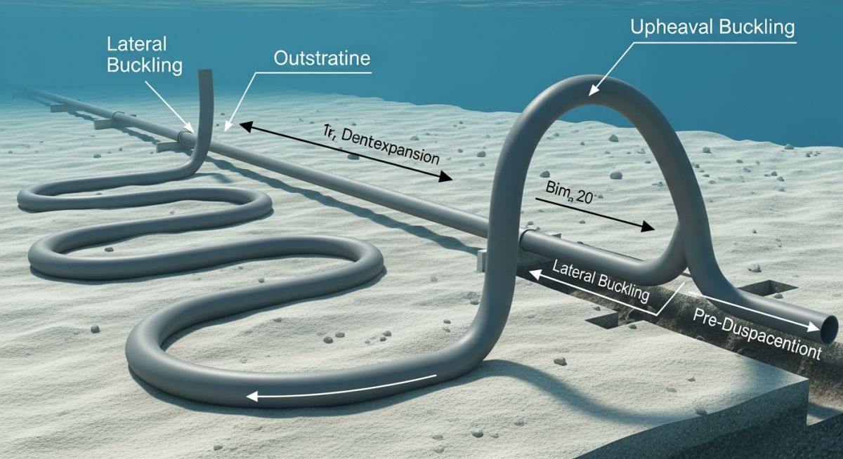
If these compressive forces exceed the structural and geotechnical resistance of the system, the pipeline will relieve this energy by buckling. This structural instability manifests in two distinct ways: lateral buckling (snaking across the seabed) or upheaval buckling (lifting vertically out of its trench). Understanding the mechanics of these two modes is not just an academic exercise; it is a safety-critical requirement for modern subsea pipeline design.
- Identify the physical triggers that cause lateral and upheaval buckling.
- Understand the role of soil-pipe interaction in governing pipeline stability.
- Learn how to apply industry standards like DNV-RP-F110 for structural design.
- Discover practical engineering mitigation strategies used in the field today.
Complete Course on
Piping Engineering
Check Now
Key Features
- 125+ Hours Content
- 500+ Recorded Lectures
- 20+ Years Exp.
- Lifetime Access
Coverage
- Codes & Standards
- Layouts & Design
- Material Eng.
- Stress Analysis
Why Do Subsea Pipelines Buckle Under Load?
To understand why a pipeline buckles, we must first look at the effective axial force (F_{eff}) acting within the pipe wall. When a pipeline is laid on the seabed, it is typically at ambient temperature. Once production starts, hot fluids pass through, raising the steel temperature. The pipeline wants to expand axially, but the friction between the pipe and the soil resists this movement. This resistance creates a massive compressive force.
The effective axial force in a fully restrained pipeline can be calculated using the following classical equation:
Where:
- H: Residual lay tension (N)
- P_i: Internal operating pressure (Pa)
- A_i: Internal cross-sectional area of the pipe (m²)
- v: Poisson’s ratio of steel (typically 0.3)
- E: Young’s modulus of steel (typically 207 GPa)
- A_s: Cross-sectional area of the steel pipe wall (m²)
- alpha: Coefficient of thermal expansion of steel (typically 1.2 x 10^-5 /°C)
- dT: Temperature difference between operating and installation conditions (°C)
When F_{eff} becomes highly compressive (negative in sign), the pipeline becomes structurally unstable. If the pipeline is unburied and resting on the seabed, it will buckle horizontally. This is known as lateral buckling. If the pipeline is buried in a trench to protect it from fishing gear or ice gouging, it cannot move laterally. Instead, it will buckle upward, pushing through the soil cover. This is known as upheaval buckling.
In my project reviews, I often see engineers treat soil parameters as static values. Soil-pipe interaction is highly non-linear and dynamic. Overestimating soil resistance can lead to unexpected upheaval buckling, while underestimating it can cause uncontrolled lateral buckles that overstress the pipe joints. Always perform sensitivity analyses on soil friction coefficients.
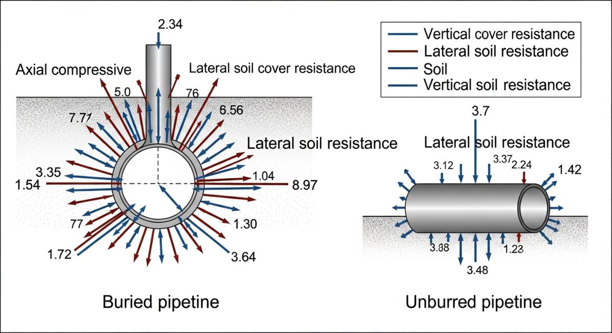
The Role of Soil Resistance in Buckling Behavior
The behavior of both lateral and upheaval buckling is heavily governed by the surrounding soil. For lateral buckling, the key parameters are the lateral and axial soil-pipe friction coefficients. For upheaval buckling, the critical parameter is the vertical uplift resistance of the backfill soil. If the vertical uplift force exerted by the expanding pipeline exceeds the downward weight of the soil cover and the pipe’s own submerged weight, upheaval buckling occurs.
According to the classical Hobbs’ formulations, the critical buckling force (P_{cr}) for a buried pipeline experiencing upheaval buckling can be simplified as:
Where I is the moment of inertia of the pipe and w_sub is the total submerged downward force per unit length, which includes the submerged weight of the pipeline and the uplift resistance of the soil cover. This highlights why the depth of cover and soil compaction are so critical in preventing vertical movement.
Key Differences Between Buckling Modes
To design safe subsea systems, we must clearly distinguish between these two phenomena. The table below outlines the primary differences in physical behavior, design drivers, and typical mitigation methods.
| Parameter | Lateral Buckling | Upheaval Buckling |
|---|---|---|
| Primary Direction | Horizontal (across the seabed) | Vertical (upward out of trench) |
| Pipeline Condition | Unburied or exposed on seabed | Buried in a trench or backfilled |
| Critical Soil Resistance | Lateral and axial soil friction | Vertical uplift soil resistance |
| Failure Mechanism | Excessive bending strain, fatigue | Rapid vertical snap, exposure to hazards |
| Mitigation Philosophy | Controlled triggering (snaking) | Prevention (rock dump, deep trenching) |
This matrix maps the core technical entities, structural acronyms, and physical parameters used in pipeline buckling design, along with their hyperlinked standard references.
| Technical Entity | Acronym / Symbol | Physical Parameter | Standard Reference |
|---|---|---|---|
| Effective Axial Force | F_eff / S | Compressive load (N) | DNV-RP-F110 |
| High-Pressure High-Temp | HPHT | Operating environment | ASME B31.8 |
| Uplift Soil Resistance | q_u | Soil vertical limit (N/m) | DNV-RP-F114 |
| Critical Buckling Force | P_cr | Instability threshold (N) | ASME B31.4 |
How to Verify Pipeline Buckling Mitigation Designs?
When reviewing pipeline designs for HPHT applications, I use a structured checklist to ensure that all potential failure modes have been addressed. This checklist helps verify that both lateral and upheaval buckling risks are mitigated before construction begins.
-
Validate Thermal Profile: Ensure the maximum operating temperature (T_{max}) and pressure (P_{max}) profiles are accurately modeled along the entire pipeline length.
-
Confirm Geotechnical Data: Verify that soil boring tests provide upper-bound and lower-bound values for both lateral friction and vertical uplift resistance.
-
Assess Out-of-Straightness (OOS): Review the seabed bathymetry and trenching profiles to identify localized vertical or horizontal deviations that act as buckling initiators.
-
Evaluate Mitigation Triggers: If using lateral buckling triggers (e.g., sleeper berths or snake-lay configurations), verify that the spacing and height are optimized to control bending strains.
-
Verify Rock Dump Design: For buried pipelines, ensure the rock dump grading and thickness provide a sufficient safety factor against vertical uplift under peak operating loads.
Field Case Study: Real-World Application
During a North Sea development project, a 10-inch gas injection pipeline operating at 120°C was buried in a 1.2-meter deep trench. During commissioning, post-lay survey data revealed localized vertical deviations (out-of-straightness) caused by hard clay formations on the trench floor. Finite element analysis indicated that these vertical imperfections would trigger premature upheaval buckling, risking pipeline exposure and potential fatigue failure from hydrodynamic loads.
To mitigate the risk, we designed a targeted rock-dumping campaign. Using the survey data, we identified the exact coordinates of the critical vertical imperfections. We applied a graded rock cover with a specific gravity of 2.6 to provide the necessary downward force. This increased the critical buckling force (P_{cr}) beyond the maximum operating effective axial force. The pipeline has now been operating safely for over eight years without any vertical displacement or loss of containment.
This case highlights the importance of combining pre-lay predictive modeling with real-time post-lay survey data. Without the post-lay survey, the localized trench imperfections would have gone unnoticed, leading to a high-risk operational failure.
Frequently Asked Engineering Questions
What is the main difference between lateral and upheaval buckling?
How does internal pressure contribute to pipeline buckling?
Why is lateral buckling sometimes allowed while upheaval buckling is prevented?
What role does soil “out-of-straightness” play in upheaval buckling?
What are the most common mitigation methods for upheaval buckling?
Which industry standards govern the design of pipeline buckling?
===
